+24V DC
24V RTN
RELAY COM
RELAY N.O.
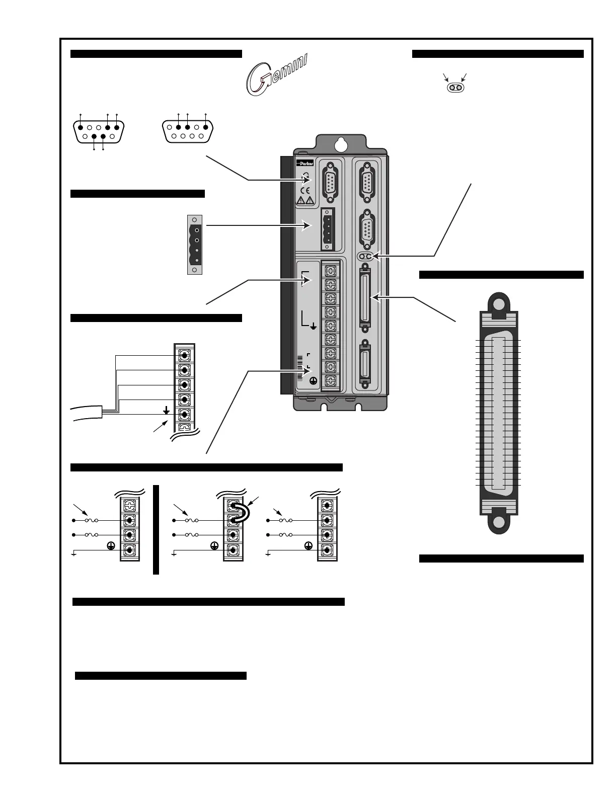
COMPUMOTOR
DATA BUS OUT DRIVE I/O MOTOR FEEDBACKDATA BUS IN
RS-232/485
GT-L5/8
STEPPER
A+
A–
B+
B–
N/C
N
L1
MOTOR
120V
Male
Pins
To configure all drive parameters, connect a PC or HPC to this
port. Use Motion Planner or Pocket Motion Planner for drive
configuration.
+24VDC provides keep alive
power to drive
When drive is enabled, it
holds relay closed.
Relay rating: 5A at 24VDC or
120VAC.
If drive is faulted or disabled,
relay will open. (Typical use:
control of motor brake.)
Motor Output Connections – see page 13
AC Input Connections– see page 14
RS-232/485 Connector – Configuration Port: see page 34
50 Pin DRIVE I/O Connector – see page 50
Troubleshooting – see page 39
+24VDC/Relay Connector – see page 32
6789
21 345
Rx Tx Gnd
RS-232 Connections
21 345
6789
Rx-
(RD A)
Tx-
(TD A)
GndRx+
(RD B)
Tx+
(TD B)
RS-485 Connections
+24V DC
24V RTN
RELAY COM
RELAY N.O.
Drive terminals: #8 (M4)
Mating terminals:
spade fork, 0.325"
maximum width.
Gemini GT6
Digital Stepper
Controller/Drive
✵
✵
Operating Temperature Still Air: 45°C (113°F)
Moving Air: 50°C (122°F)
Minimum: 0°C (32°F)
Storage Temperature: -40°C – 85°C (-40°F – 185°F)
Humidity: 0 – 95%, non-condensing
Environmental Specifications – see page 49
Short Circuit Protection
Inrush Current Protection
Drive Overtemperature Protection
Undervoltage Protection
Regeneration Protection
Protective Circuits – see page 58
LED Color:
Left Right Indicated State
Off Yel Initialization
Red (flash) Off Awaiting flash download
Grn (flash) Yel (flash) Programming flash memory
Red Grn Keep alive mode
Grn Grn (flash) Incoming steps (variable rate)
Grn Yel/Grn (flash)Autorun mode
Red Off Drive not enabled
Drive faulted
Grn Off Drive ready
Yellow/GreenGreen/Red
LEDs – see page 40
A+
A–
B+
B–
Motor Cable
Drive
Terminals
A+
A–
B+
B–
Earth
Motor
Wires
GT6-L5/8 GT6-U5/8
95 – 132VAC
V DBL
L2/N
L1
95 – 132VAC
Fuses
Connect jumper for
120VAC operations
N/C
N
L1
Fuses
Drive terminals: #8 (M4).
Mating terminals: spade fork, 0.325" maximum width.
V DBL
L2/N
L1
190 – 264VAC
Fuses
Commonly used status commands (binary status bits are
numbered 1 to n, from left to right):
TERRLG Error log reports the last 10 error conditions
(cleared with CERRLG).
TAS General report, including fault conditions.
TASX Additional report of conditions not covered with
TAS.
TCS If TASX bit #7 or bit #28 is set, you can identify
the cause with TCS.
TINO Bit #6 indicates status of Enable input ("1" = OK
to enable drive).
TIN Status of digital inputs, including end-of-travel
inputs.
TOUT Status of digital outputs.
You must configure all motor parameters. Be sure to follow
the drive configuration procedure (see
Chapter 2 Installation
).
Any fault condition causes the drive to shut down.
The drive can not be enabled (DRIVE1) unless the Enable
input is grounded and the Reset input is not grounded.
Use one of three methods to reset the drive (all command
settings are remembered after reset):
Issue the RESET command.
Momentarily close the Reset input.
Cycle power to the drive.
Output Ground
Output 6
Output 5
Output Ground
Output 4
Output 3
Output Ground
Output 2
Output Ground
Output 1
Input Ground
Input 8
Input 7
Input 6
Input Ground
Input 5
Input 4
CNTRL-P: 4 – 8
Input Ground
Input 3
Input Ground
Input 2
Input 1
CNTRL-P: 1 – 3
VINref
Analog Ground
Reserved
Reserved
Analog Output B
Analog Output A
Digital Ground
Reserved
Reserved
Direction– Out
Direction+ Out
Step– Out
Step+ Out
Reserved
Reserved
Reserved
Reserved
Reserved
Reserved
Digital Ground
Digital Ground
Reserved
Reserved
Reset
Digital Ground
Enable
25
24
23
22
21
20
19
18
17
16
15
14
13
12
11
10
9
8
7
6
5
4
3
2
1
25
24
23
22
21
20
19
18
17
16
15
14
13
12
11
10
9
8
7
6
5
4
3
2
1
50
49
48
47
46
45
44
43
42
41
40
39
38
37
36
35
34
33
32
31
30
29
28
27
26

 Loading...


