K3.1.142k Manual NitroFlow Lab - 9 -
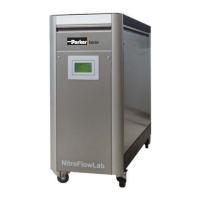
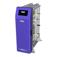
3.3 Parts
1 Removable Front Cover 6 Main Switch / Circuit Breaker
2 Oxygen Sensor 7 Electrical Supply Cable Inlet
3 Pressure Control Valve (PCV) 8 Nitrogen Outlet
4 Purity Adjustment Valve (FCV) 9 Ventilation Outlet (Keep Clear)
5 Touch Screen Display
3.4 Process diagram
The generator can be connected directly to the nitrogen consumer (Fig. 3-3) or to a buffer vessel (Fig. 3-4).
Fig. 3-3
Fig: 3-4
NitroFlow
®
Lab
Nitrogen
Consumer
NitroFlow
®
Lab
Buffer
Vessel
Nitrogen
Consumer