Do you have a question about the Parker GVI Series and is the answer not in the manual?
Details about the Parker Hannifin manufacturing location in Germany.
Disclaimer regarding the accuracy and liability of the publication's content.
Explains the purpose, scope, and structure of the manual, including definitions and warnings.
Identifies and explains safety symbols used on Parker's products.
Procedures and contact information for handling warranty claims and returns.
Refers to the sales agreement for the complete product warranty statement.
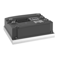
Describes the GVI product range consisting of frames C, D, and E.
Identifies and labels the main components of the GVI unit.
Details the terminal posts designed for ring lug and threaded connections.
Explains the information found on the GVI product identification label.
Describes the LED status indicator for diagnostic information and troubleshooting.
Explains how the GVI is cooled via a cold plate heat sink.
Provides guidelines for integrating the motor controller into a vehicle system.
Details precautions for protecting the GVI from dust and moisture.
Specifies requirements for effective heat dissipation from the GVI.
Explains the function and requirement of an emergency stop switch for GVI applications.
Discusses general aspects and specific input requirements for motor feedback sensors.
Explains the use of temperature sensors for monitoring motor winding temperature.
Covers the guidelines for mounting two GVI units together using a bus bar.
Refers to the chapter describing the GVI's I/O interface details.
Outlines the procedures for configuring and commissioning the GVI for application use.
Provides information on integrating the GVI into the vehicle's safety system compliance.
Introduces the standard monitoring features of the motor controller.
Explains power stage and motor temperature monitoring for damage prevention.
Details current measurement for motor phases and overload protection.
Provides voltage monitoring data ranges and trip levels for different GVI models.
Notes the default timeout value for CANopen PDO monitoring.
Specifies the default time limit for pre-charging the filter capacitor bank.
General instructions for installation and maintenance of the motor controller.
Recommends minimal periodic inspection and maintenance items for the controller.
Guides on how to replace the on-board fuse for the motor controller.
Provides instructions for safely removing the GVI unit from the vehicle.
Details the procedure for installing the GVI motor controller into a vehicle.
Describes recommended assembly materials and procedures for connecting terminal posts.
Outlines general procedures for startup and verification after installation.
Explains the LED status indicator's appearance and corresponding drive conditions.
Discusses best practices for routing I/O and signal cables to minimize noise and ensure proper function.
Provides guidelines for selecting and connecting power cables to prevent overheating.
Covers precautions for preventing damage from electrostatic discharge (ESD).
Details considerations for proper start-up and turn-off sequences of the motor controller.
Instructions to check motor phase cable connections to U, V, and W terminals.
Refers to specifications for assembly instructions of the harness side plug connector.
Displays the pinout configuration for the GVI 35-pin connector.
Describes the function and protection of the KEY_INPUT for logic circuitry power.
Explains the function and protection of digital inputs for connecting switches.
Details the use of HW ID inputs for selecting parameter sets and functions.
Covers the function, protection, and circuit for analog inputs used for speed or potentiometers.
Describes the multi-function encoder inputs for motor feedback sensors.
Explains the function, modes, and protection of open drain outputs for service control.
Details the function, protection, and circuit for high side switches for safety functions.
Describes the input for measuring motor winding temperature using sensors like KTY84.
Details the supply for external sensors and analog inputs, including protection and circuit.
Explains the function and usage of the sensor supply ground pin for reference.
Covers the function, protection, and circuit for the CAN communication interface.
Lists general specifications for the GVI, including motor types, communication, and temperature ranges.
Details the current and power output ratings for different GVI models and frames.
Specifies the nominal, operating, and instantaneous voltage requirements for GVI models.
Provides detailed technical data for various GVI I/O interfaces.
Covers physical properties of the GVI, including weight and dimensions for each frame.
Lists environmental tests and standards the GVI complies with.