GVI Product Manual: Frames C, D & E
16 192-300300N1 GVI Frames C, D & E 2019-9
7.3.1. GVI with cold plate heat sink
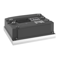
The motor controller with a cold plate heat sink is cooled through surface contact with the vehicle body.
Specifications for surface roughness and surface flatness where motor controller is mounted to the vehicle
body must be observed (see chapter 13.5.3. Application of thermal grease to the cold plate heat sink before
mounting the motor controller will achieve the best cooling effect.
The required heat sink-to-vehicle mounting surface thermal resistance shown in Table 3 must be achieved
by the installation in order for the motor controller to meet the published current ratings in the application.
For recommendations regarding mounting of the motor controller see chapters 7.5 and 10.5.
GVI-C024-0350, GVI-C024-0550, GVI-C048-0280
GVI-C024-0550, GVI-D048-0450, GVI-D048-0550, GVI-
080-D0230, GVI-D080-0350, GVI-D080-0400
GVI-E048-0700, GVI-E080-0500, GVI-E080-0700
Table 3 Required thermal resistance for flat heat sink
7.4 Orientation
NOTE
The vibration test of the GVI does not include a horizontal mounting position with the I/O
connector facing downwards.
The motor controller can be mounted vertically or horizontally with the I/O connector facing upwards. Care
should be taken to ensure access to the I/O connector, terminals and LED indicator.
When multiple motor controllers are used in an application each of the units must be arranged such that they
have sufficient cooling for the required duty cycle.
Consideration should be given to accessibility and visibility of the on-board LED status indicator (1, Figure 9)
for maintenance purposes.
Figure 9. LED status Indicator, (the surrounding label may vary)

 Loading...