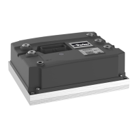
GVI Product Manual: Frames C, D & E
4 192-300300N1 GVI Frames C, D & E 2019-9
7.12 Emergency stop switch ......................................................................... 21
7.13 Motor feedback sensor .......................................................................... 22
7.13.1. General .............................................................................................................. 22
7.13.2. Sinusoidal Motor Speed Sensor Input ........................................................... 22
7.14 Motor temperature sensor..................................................................... 24
7.15 Double-mounting of GVI ........................................................................ 24
7.16 I/O interface ............................................................................................ 24
7.17 Start-up and Commissioning ................................................................ 24
7.17.1. Configuring the motor controller for the application ................................... 24
7.18 Incorporation of GVI in the vehicle safety system .............................. 25
7.18.1. Motor controller functions .............................................................................. 25
7.18.2. MTTFd ............................................................................................................... 25
7.18.2.1 How to apply MTTFd calculations in an application ............................. 25
7.18.2.2 Travel and brake control ....................................................................... 26
7.18.2.3 MTTF and MTTFd values for different functions................................... 27
7.18.2.4 Power stage .......................................................................................... 27
7.18.3. Default parameters, EEPROM considerations .............................................. 28
8. I/O interface description ....................................................................... 29
8.1 Mating connector specification ............................................................ 29
8.1.1. Part numbers .................................................................................................... 29
8.2 GVI 35 pin Premium pinout ................................................................... 29
8.3 Key_Input ................................................................................................ 30
8.3.1. Function ............................................................................................................ 30
8.3.2. Protection ......................................................................................................... 30
8.4 Digital input ............................................................................................ 30
8.4.1. Function ............................................................................................................ 30
8.4.2. Protection ......................................................................................................... 30
8.4.3. Circuit ................................................................................................................ 31
8.5 HW ID1 and ID2 inputs ........................................................................... 31
8.5.1. Function ............................................................................................................ 31
8.5.2. Protection ......................................................................................................... 31
8.5.3. Circuit ................................................................................................................ 32
8.6 Analog Inputs ......................................................................................... 32
8.6.1. Functions .......................................................................................................... 32
8.6.2. Protection ......................................................................................................... 32
8.6.3. Circuit ................................................................................................................ 32
8.7 Encoder input ......................................................................................... 33
8.7.1. Function ............................................................................................................ 33
8.7.2. Protection ......................................................................................................... 33
8.7.3. Circuit ................................................................................................................ 33
8.8 Open Drain Output ................................................................................. 34
8.8.1. Function ............................................................................................................ 34
8.8.2. Protection ......................................................................................................... 35
8.8.3. Circuit ................................................................................................................ 35
8.9 High Side IN and Out ............................................................................. 36
8.9.1. Function ............................................................................................................ 36
8.9.2. Protection ......................................................................................................... 36
8.9.3. Circuit ................................................................................................................ 37
8.10 Motor temperature measurement input ............................................... 37
8.10.1. Function ............................................................................................................ 37

 Loading...