Service/Spare Parts Manual
Series V12
MSG30-5506-M1/UK
13
Parker Hannifin
Pump & Motor Division Europe
Trollhättan, Sweden
Parker Hannifin
Pump & Motor Division Europe
Trollhättan, Sweden
Aassembling, end cap
13
Parker Hannin
PumpandMotorDivision
Trollhättan,Sweden
ServiceManual
Series V12
HY30-5506-M1/UK
37.Assemblethecontrolcoverassy.Make
suretheO-ringsandcheckvalveballsarein
correctposition.
38.Torquethescrewsto65±10Nmfor
V12-60--110,105±20NmforV12-160.
39.Assemblethecoverassy.Makesurenot
todamagetheO-ring.
40.Torquethescrewsto65±10Nmfor
V12-60--110,105±20NmforV12-160.
41.Assemblethevalvesegmentintheend
cap.Theslotinthevalvesegmentagainst
thecoverside.
Assembling, end cap (new version)
Assembling, end cap (new version)
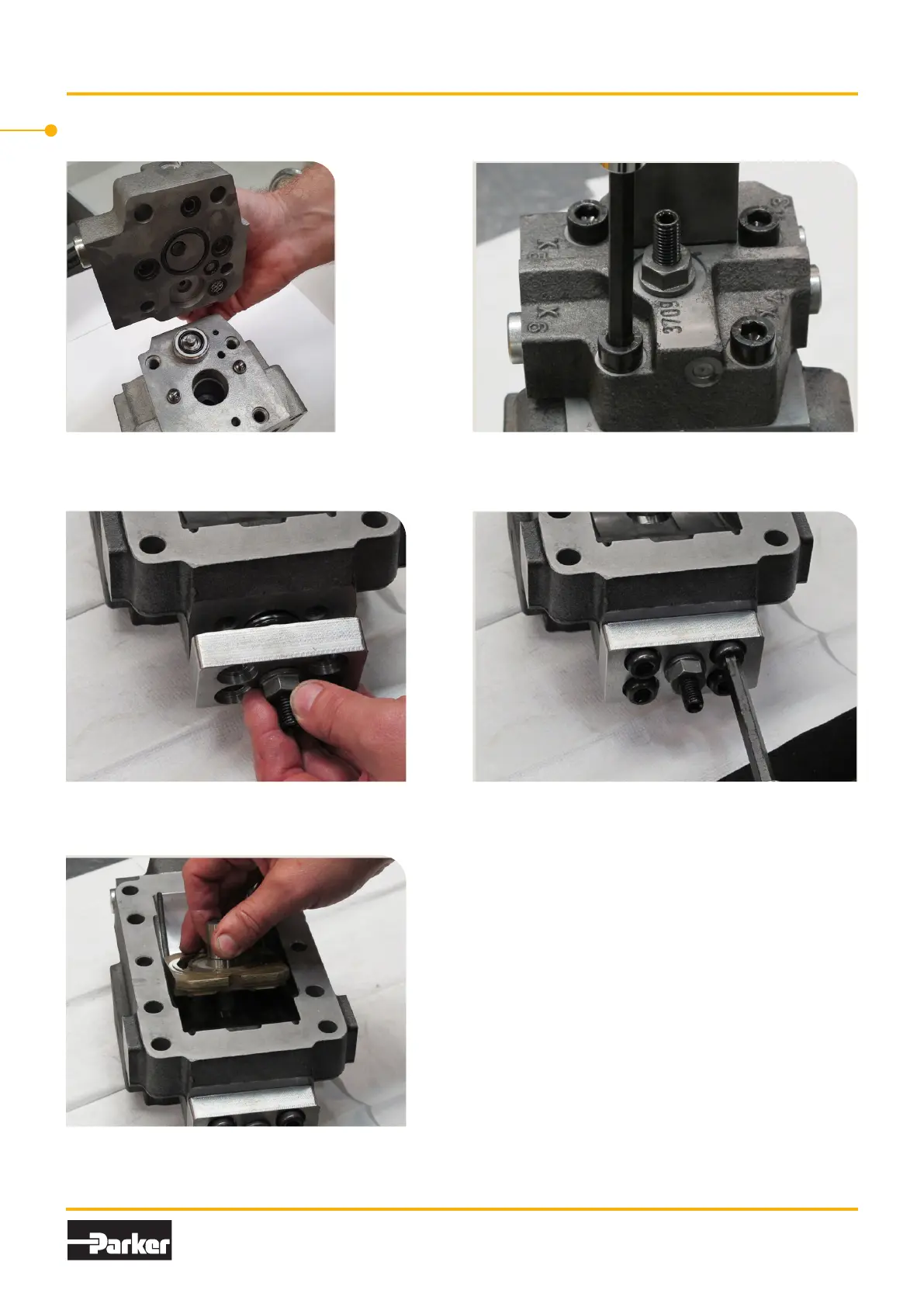
37. Assemble the control cover assy. Make sure
the O-rings and check valve balls are in cor-
rect position.
38. Torque the screws to 65±10 Nm for V12-60 – -110,
105±20 Nm for V12-160.
39. Assemble the cover assy. Make sure not to
damage the O-ring.
40. Torque the screws to 65±10 Nm for V12-60 – -110,
105±20 Nm for V12-160.
13
Parker Hannin
PumpandMotorDivision
Trollhättan,Sweden
ServiceManual
Series V12
HY30-5506-M1/UK
37.Assemblethecontrolcoverassy.Make
suretheO-ringsandcheckvalveballsarein
correctposition.
38.Torquethescrewsto65±10Nmfor
V12-60--110,105±20NmforV12-160.
39.Assemblethecoverassy.Makesurenot
todamagetheO-ring.
40.Torquethescrewsto65±10Nmfor
V12-60--110,105±20NmforV12-160.
41.Assemblethevalvesegmentintheend
cap.Theslotinthevalvesegmentagainst
thecoverside.
Assembling, end cap (new version)
41. Assemble the valve segment in the end cap.
The slot in the valve segment against the co-
ver side.
13
Parker Hannin
PumpandMotorDivision
Trollhättan,Sweden
ServiceManual
Series V12
HY30-5506-M1/UK
37.Assemblethecontrolcoverassy.Make
suretheO-ringsandcheckvalveballsarein
correctposition.
38.Torquethescrewsto65±10Nmfor
V12-60--110,105±20NmforV12-160.
39.Assemblethecoverassy.Makesurenot
todamagetheO-ring.
40.Torquethescrewsto65±10Nmfor
V12-60--110,105±20NmforV12-160.
41.Assemblethevalvesegmentintheend
cap.Theslotinthevalvesegmentagainst
thecoverside.
Assembling, end cap (new version)

 Loading...