Service/Spare Parts Manual
Series V12
MSG30-5506-M1/UK
7
Parker Hannifin
Pump & Motor Division Europe
Trollhättan, Sweden
Parker Hannifin
Pump & Motor Division Europe
Trollhättan, Sweden
Assembling, control cover
7
Parker Hannin
PumpandMotorDivision
Trollhättan,Sweden
ServiceManual
Series V12
HY30-5506-M1/UK
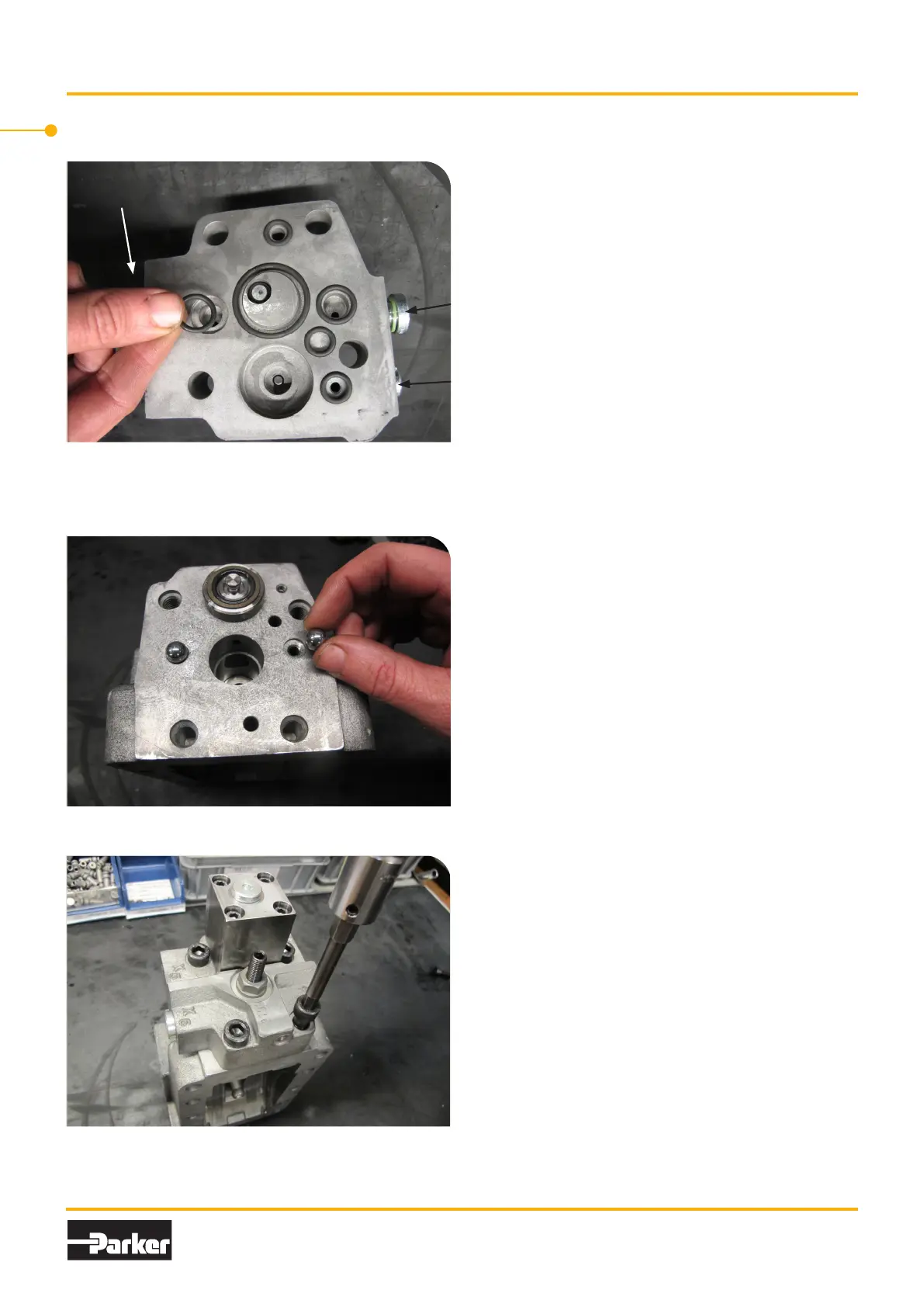
Assembling, control cover, New version without valve cones and valve guides
DIN38±8Nm
SAE25±5Nm
A.AssembletheO-ringsandplugsthatare
requiredforthespeciccontrolcover.AH-
controlisshowninthepicture.
DIN13±3Nm
(AHI-I)
DIN38±8Nm
SAE25±5Nm
Thecontrolcovershowninpictureisbi-
directional.
B.Assemblethecheckballs.
C.Assemblethecontrolcoverandtorque
thescrewsto65±10NmforV12-60,-80
and-110.105±20NmforV12-160.
Assembling, control cover, New version without valve cones and valve guides
A. Assemble the O-rings and plugs that are required
for the specific control cover. AH-control is shown
in the picture.
.
B. Assemble the check balls.
7
Parker Hannin
PumpandMotorDivision
Trollhättan,Sweden
ServiceManual
Series V12
HY30-5506-M1/UK
Assembling, control cover, New version without valve cones and valve guides
DIN38±8Nm
SAE25±5Nm
A.AssembletheO-ringsandplugsthatare
requiredforthespeciccontrolcover.AH-
controlisshowninthepicture.
DIN13±3Nm
(AHI-I)
DIN38±8Nm
SAE25±5Nm
Thecontrolcovershowninpictureisbi-
directional.
B.Assemblethecheckballs.
C.Assemblethecontrolcoverandtorque
thescrewsto65±10NmforV12-60,-80
and-110.105±20NmforV12-160.
C. Assemble the control cover and torque the screws
to 65±10 Nm for V12-60, -80 and -110. 105±20 Nm
for V12-160.
7
Parker Hannin
PumpandMotorDivision
Trollhättan,Sweden
ServiceManual
Series V12
HY30-5506-M1/UK
Assembling, control cover, New version without valve cones and valve guides
DIN38±8Nm
SAE25±5Nm
A.AssembletheO-ringsandplugsthatare
requiredforthespeciccontrolcover.AH-
controlisshowninthepicture.
DIN13±3Nm
(AHI-I)
DIN38±8Nm
SAE25±5Nm
Thecontrolcovershowninpictureisbi-
directional.
B.Assemblethecheckballs.
C.Assemblethecontrolcoverandtorque
thescrewsto65±10NmforV12-60,-80
and-110.105±20NmforV12-160.
DIN 38±8 Nm
SAE 25±5 Nm
DIN 13±3 Nm
(AHI-I)
The control cover shown in picture is bi-directional.

 Loading...


