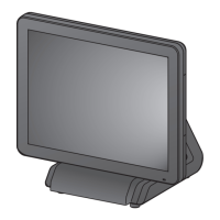
16
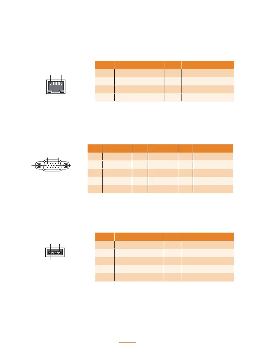
Connector Pin Dene
This section describes the connectors pin dene.
VGA Connector Pin Dene
1 5
6
10
11 15
Pin Signal Pin Signal Pin Signal
1 Red 6 AGND 11 N/A
2 Green 7 AGND 12 DDC DAT
3 Blue 8 AGND 13 Horizontal Sync
4 N/A 9 N/A 14 Vertical Sync
5 GND 10 GND 15 DDC CLK
COM Connector Pin Dene
Pin Signal Pin Signal
1 +5V/ +12V 5 RxD
2 DCD 6 TxD
3 DTR 7 CTS
4 GND 8 RTS
*It could be supplied with power with 5V or 12V via Jumper or BIOS-setting.
1 8
USB 3.0 Connector Pin Dene
9
1
5
4
Pin Signal Pin Signal
1 USB Vcc 5 StdA_SSRX-
2 USB - 6 StdA_SSRX+
3 USB + 7 GND
4 USB GND 8 StdA_SSTX-
9 StdA_SSTX+