Installing the Patton SmartNode VoIP Gateway 26
SmartNode 4170 User Manual 3 • SmartNode Installation
Connecting the Power Supply
Do the following to connect the main power to the Model SN4170:
Note Do not connect the power cord to the AC Mains at this time.
1. Insert the female end of the AC power supply cable to the mains port (see figure 2 on page 16).
2. Verify that the AC power cord included with your device is compatible with local standards. If it is not,
refer to
“Contacting Patton for Assistance” on page 36 to find out how to replace it with a compatible
power cord.
3. Connect the male end of the power cord to an appropriate power outlet.
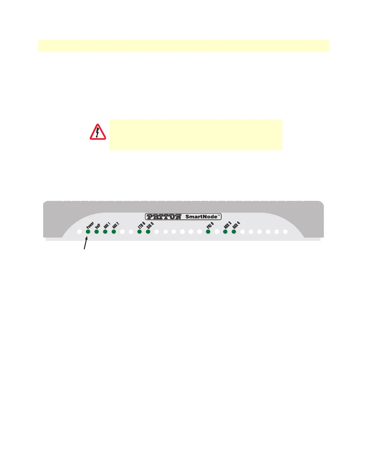
Figure 7. Power LED
4. Verify that the green Power LED is lit (see figure 7). Blinks fast during bootloader phase and blinks slow
during boot process of Trinity Software. Becomes solid when the system is up and running.
Congratulations, you have finished installing the SmartNode E1/T1 PRI VoIP Gateway! Now go to Chapter 4,
“Initial Configuration” on page 27.
There are no user-serviceable parts in the power supply section
of the model SN4170. Contact Patton Electronics Technical
Support at support@patton.com for more information
CAUTION