ISDN PRI (E1/T1) 49
SmartNode 4170 User Manual C • Cabling
ISDN PRI (E1/T1)
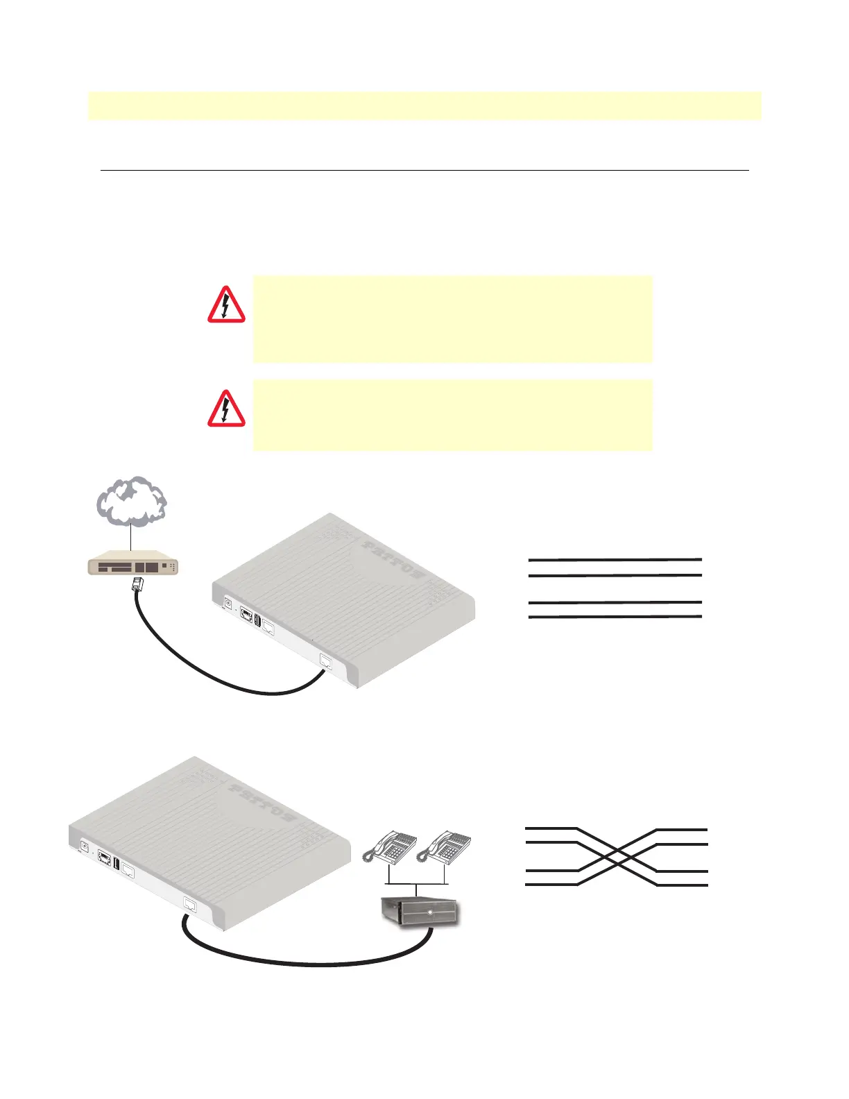
The E1/T1 PRI port 0/0 uses the (LE) pinout. In most cases, a straight-through RJ-45 to RJ-45 can be used to
connect the device to a PSTN NT. However, pinouts may vary depending on the pinout being used by the NT.
If PRI port 0/0 will be connected to a PBX, usually a PRI cross-over cable is required.
See the cabling details in figure 15.
The pin-out of a cross-over cable in illustrated in figure 16
Figure 15. PSTN NT Cabling
Figure 16. Crossover cable pinout
Hazardous network voltages are present in the PRI cables. If
you detach the cable, detach the end away from the Smart
-
Node or interface card first to avoid possible electric shock. Net-
work hazardous voltages may be present on the device in the
area of the PRI port, regardless of when power is turned OFF.
To prevent damage to the system, make certain you connect
the PRI cable to the PRI port only and not to any other RJ-45
socket.
CAUTION
CAUTION
12V, 1A
PRI
0
/0
ETH 0/0
USB
Co
nsole
Reset
33
4
4
5
5
6
6
1
2
7
8
1
2
7
8
TX Tip
TX Ring
N/C
RX Tip
RX Ring
RX Ring
TX Tip
RX Tip
TX Ring
N/C
N/C
N/C
N/C
N/C
N/C
*N/C = No connection*
PSTN NT
SmartNode
Port 0/0
NT
PSTN
12V, 1A
PRI 0/
0
ETH 0/0
USB
Console
Reset
PRI PBX
33
4
4
5
5
6
6
1
2
7
8
1
2
7
8
RX Tip
RX Ring
N/C
TX Tip
TX Ring
RX Ring
TX Tip
RX Tip
TX Ring
N/C
N/C
N/C
N/C
N/C
N/C
*N/C = No connection*
PBX
SmartNode
Port 0/0
N/C