Chapter 7 Appendix
(1) Operation of a relay explained
(2) Fail open & fail closed locks explained
Appendix (1) Operation of a relay explained
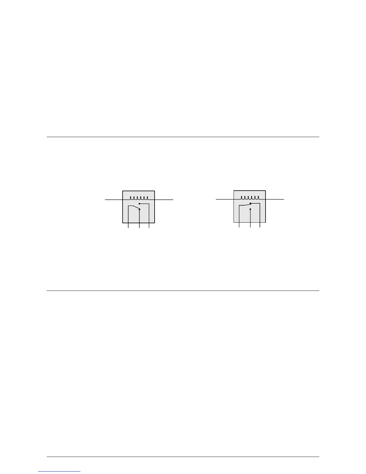
The Switch2 ACU contains one relay and has output terminals common (COM), normally open
(N.O.) and normally closed (N.C.).
COM N.C. N.O
Coil not energised
(natural state)
COM N.C. N.O
Coil energised
In the de-energised state, COM and N.C. are connected. When the coil is energised, the relay
operates and COM and N.O. are connected. As soon as the coil is de-energised the connection
returns to the COM and N.C. position.
The output terminals COM, N.O. and N.C. are voltage free. This means that they can be used to
control power using the same supply that drives the Switch2 or may be included as part of an
independent circuit to signal other electrical devices e.g. Car Park Barrier.
Appendix (2) Fail open & fail closed locks explained
Fail open (fail safe)
Fail open devices require power to lock, i.e. if there is no power to the device it is unlocked. An
example of a fail open device is a magnetic lock (maglock).
A fail open locking device is a requirement for fire doors. This is because it is not reliant on
electrical power to unlock.
It is advisable to have a battery backup for systems using fail open devices. Otherwise a mains
power failure would lead to doors unlocking for the period of the mains failure.
Fail open devices are inefficient in terms of power consumption when compared to fail closed
devices. This is because they are powered for the majority of the time, i.e. when the door is
locked.
Fail closed (fail secure)
Fail closed devices require power to unlock, i.e. if there is no power to the device it is locked. Most
standard electric releases are fail closed.
If battery backup is not fitted, mains loss would result in doors being locked for the period of the
power failure.
Fail closed devices are more efficient that fail open devices. This is because they are only powered
when the door is unlocked.
Chapter 9 Specification 27