Chapter 3 Wiring
Readers/keypads
Power supply
Inputs
Outputs
Readers/keypads
CARDLOCK readers (5v & 12v)
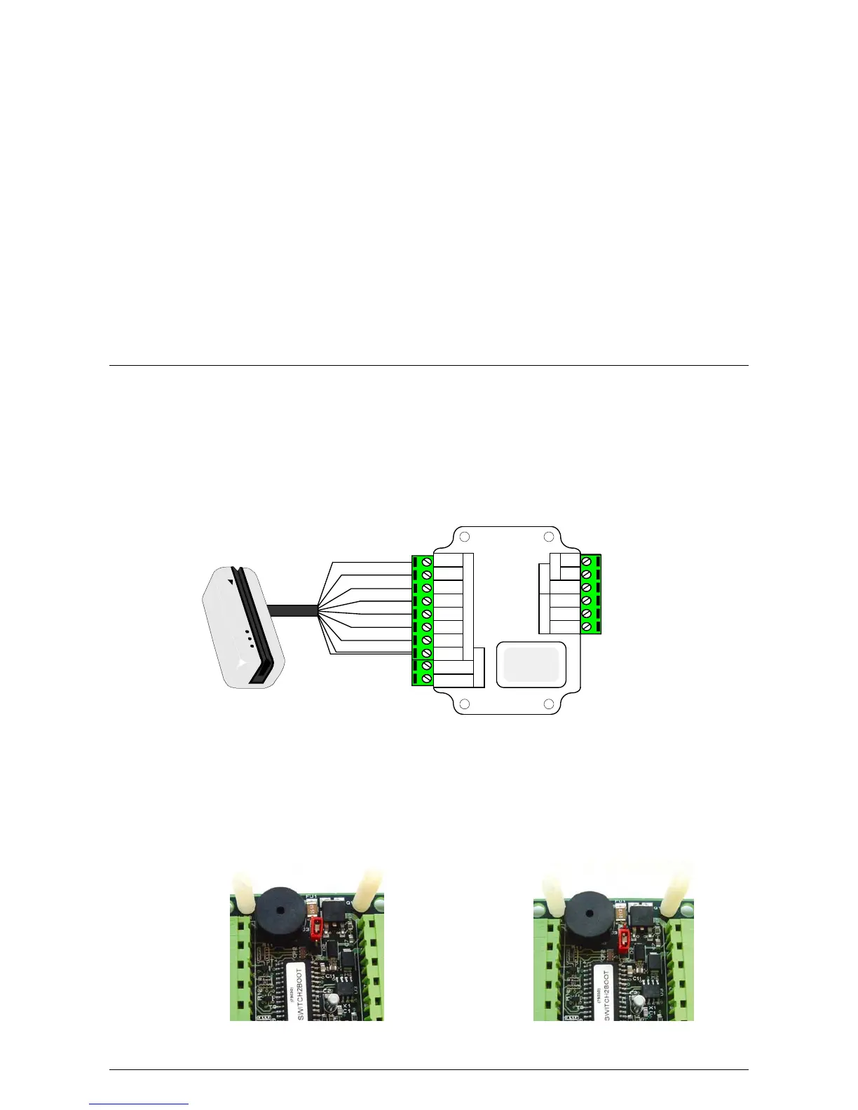
CARDLOCK readers come supplied with 5 metres of cable. The colours of the cable cores
correspond directly to the colours on the Switch2 control unit label. When extending the
cable distance beyond 5 metres, do not used twisted pair cable as the data signals may
become distorted. Belden 9540 is recommended. The screen should be connected to 0V
(Black terminal) for all readers and keypads that have a screened cable.
CARDLOCK reader
Red
Brown
Orange
Green
Yellow
Blue
Mauve
Black & White
Attach
Q.C. Label
here
Red
Brown
Orange
Green
Yellow
Blue
Mauve
Exit
Contact
Black
Card reader or keypad
12v
0v
N.C.
N.O.
Com
Bell
PowerDoor relay
Alarm
Control
unit
Inputs
witch
2
S
*IMPORTANT*
When 5v CARDLOCK readers or TOUCHLOCK SS keypads are connected to Switch2
control units with yellow wiring labels the jumper setting on the PCB must be changed
from the 12V setting to the 5V setting.
NOTE: TOUCHLOCK membrane keypads are NOT compatible with yellow label Switch2.
5V readers
12V readers
Chapter 3 Wiring 9