PAGE 26
Class 1 Medical
Rev. 2
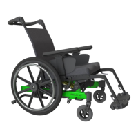
Figure 14.17: Easy-Out Plug-
In 70° Front Rigging
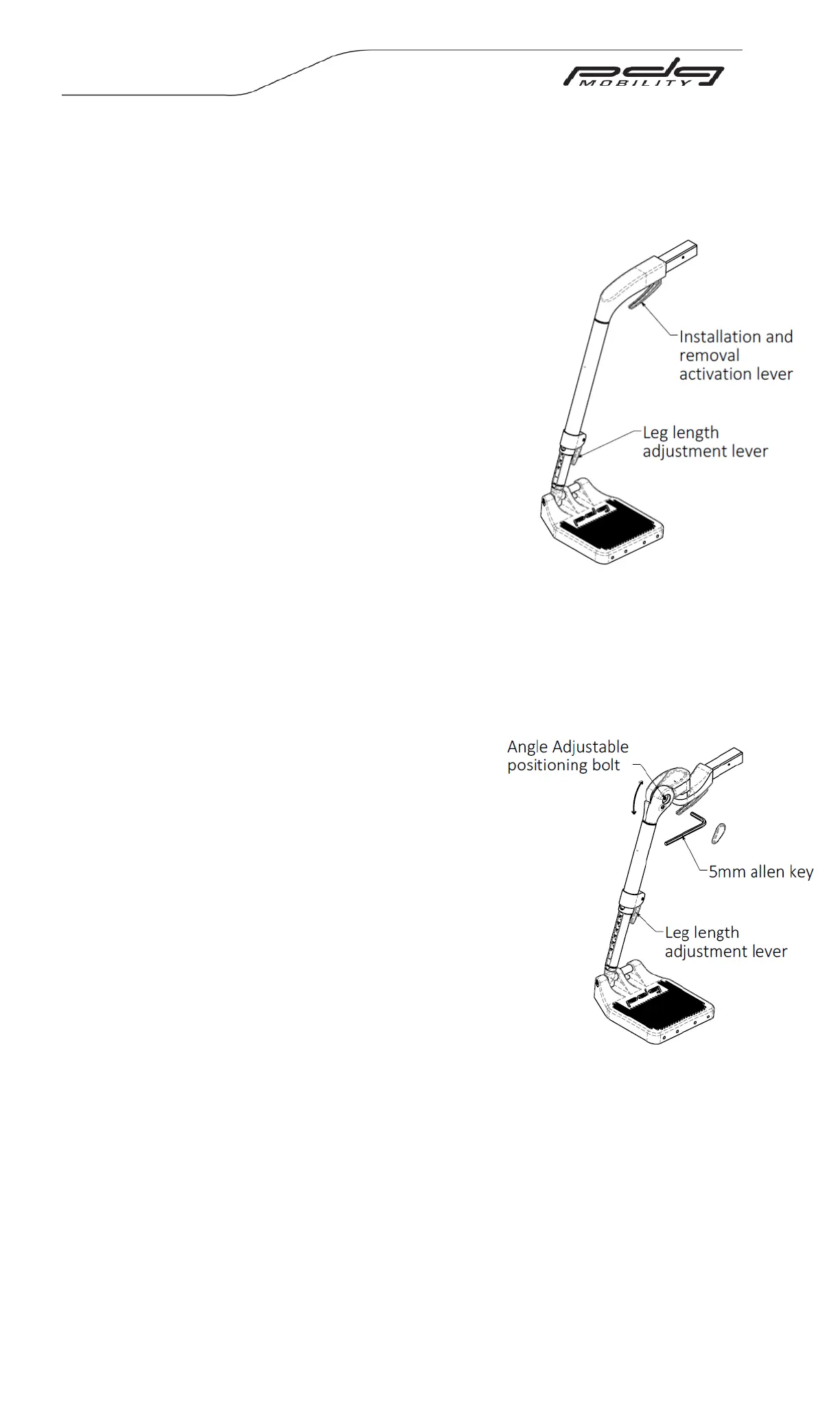
Figure 14.18: Easy-Out Angle
Adjustable Front Rigging
14.6.2 Easy-OutTM Front Rigging Footrest Assembly – Plug-in 70°, Adjustable Knee
Angle Front Rigging.
Plug-in 70° Front Rigging Footrest Assembly Installation
Installation and Removal:
a. To mount the easy out plug-in front rigging,
depress the lever located under the plug-in
and slide the front rigging into the open
square tube receiver (upper frame seat
rail). The fronting rigging will lock into
position when the lever snaps through the
hole located on the bottom of the square
receiver tube.
b. To release the front rigging, similarly
activate the trigger to disengage the lever
from the hold and slide the front rigging
forward and out of the upper frame.
Plug-In Adjustable Knee Angle Front Rigging (Optional)
Installation and Removal of this option is
the same as the Easy-out Plug-in 70 Front
Rigging.
To adjust the Knee Angle Front Rigging:
a. Remove the plastic cover on the side by
prying it off by hand.
b. Unlock the knee angle joint by loosening
the socket head fastener ½ a turn.
c. Adjust the angle of the front rigging to the
desired location.
d. Once set to the desired location, re-tighten
the socket head fastener and re-install the
plastic cover.
Footrest Height adjustment:
a. Release the footrest extension adjustment
lever. This is shown in figure 14.18.
b. Adjust the footrest extension to the desired
height.
c. Fully depress the lever to lock the footrest
extension height.
Note: Height adjustment can be performed with the individual sitting in the
wheelchair with their feet on the foot plates. The lowest point of the foot
plates should be no less than 2” from the ground or floor.
 Loading...