,m ;,]1fl::1i_ :1:1:1_,]]1[_-
_! IiI; t _1",I:I -'!:!1/ [*] L_
i. The boiler must be pressure tested as outlined in the
chapter "Place the Boiler Sections" of this manual.
2. The Supply and Return piping can be installed
before the jacket is applied. Use nipples long enough
to extend through the jacket.
;N t-"llll,,ll, lli'd I:,ll:JIL_[€
1.
2.
See Figure 21 for piping illustration.
Install Top connections sized per Table 11.
a) Model LC-04 requires one riser off the Rear
Section. Plug the 4" tapping in the top of the
Front Section.
b) Models LC-05 through LC-10 require two risers,
one off the Front and one off the Rear Section.
c) Models LC-11 and LC-12 require three risers,
one each off the Front and Rear Sections plus
one off the Tapped Intermediate Section.
d) LCE models require three or more risers.
5,
6.
7.
Counterflow Gravity systems require the boiler steam
line to enter the top of the steam main. See
Figure 20 for this special case.
Do not reduce the size or number of risers
shown. These are required for reliable operation of
the boiler. If the risers are undersized or incorrectly
placed, a sloped water line can occur in the boiler,
causing possible overheating of some sections.
Pipe the Header with an offset as shown in the
drawings. This offset prevents the expansion and
contraction of the Header from damaging the boiler
sections.
8.
9.
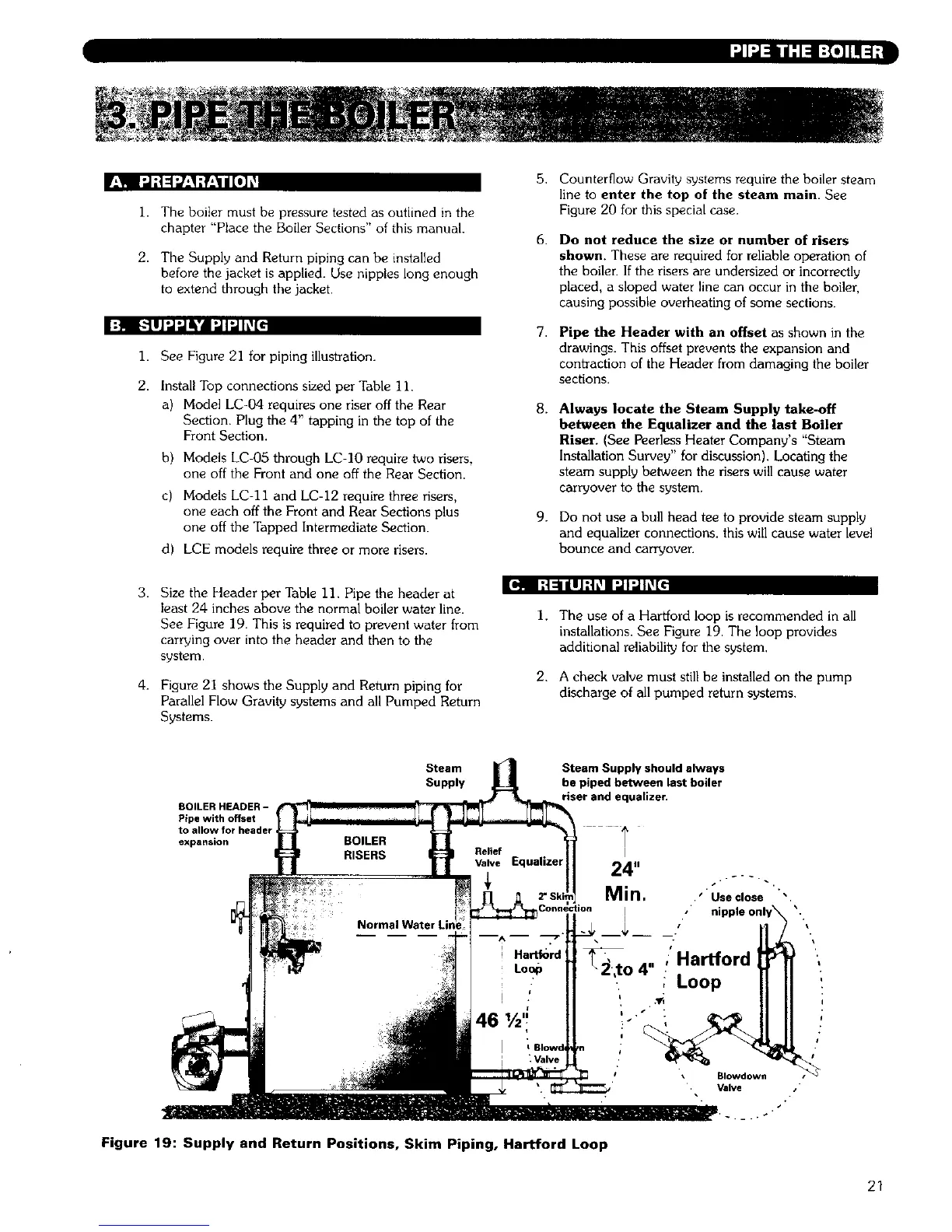
Always locate the Steam Supply take-off
between the Equalizer and the last Boiler
Riser. (See Peerless Heater Company's "Steam
Installation Survey" for discussion). Locating the
steam supply between the risers will cause water
carryover to the system.
Do not use a bull head tee to provide steam supply
and equalizer connections, this will cause water level
bounce and carryover.
Jel! I it 11ill ltl'_l fJI iI h:_lc
3.
4.
Size the Header per Table 11. Pipe the header at
least 24 inches above the normal boiler water line.
See Figure 19. This is required to prevent water from
carrying over into the header and then to the
system.
Figure 21 shows the Supply and Return piping for
Parallel Flow Gravity systems and all Pumped Return
Systems.
I. The use of a Hartford loop is recommended in all
installations. See Figure 19. The loop provides
additional reliability for the system.
2. A check valve must still be installed on the pump
discharge of all pumped return systems.
BOILER HEADER -
Pipe with offset
to allow for header
expansion
Steam
Supply
Steam Supply should always
be piped between last boiler
riser and equalizer.
I
24"
Min. ." Use close
x i
To 4" " Hartford
, Loop
Figure 19: Supply and Return Positions, Skim Piping, Hartford Loop
Blowdown /"
Valve .
/+
I
!
21