3.
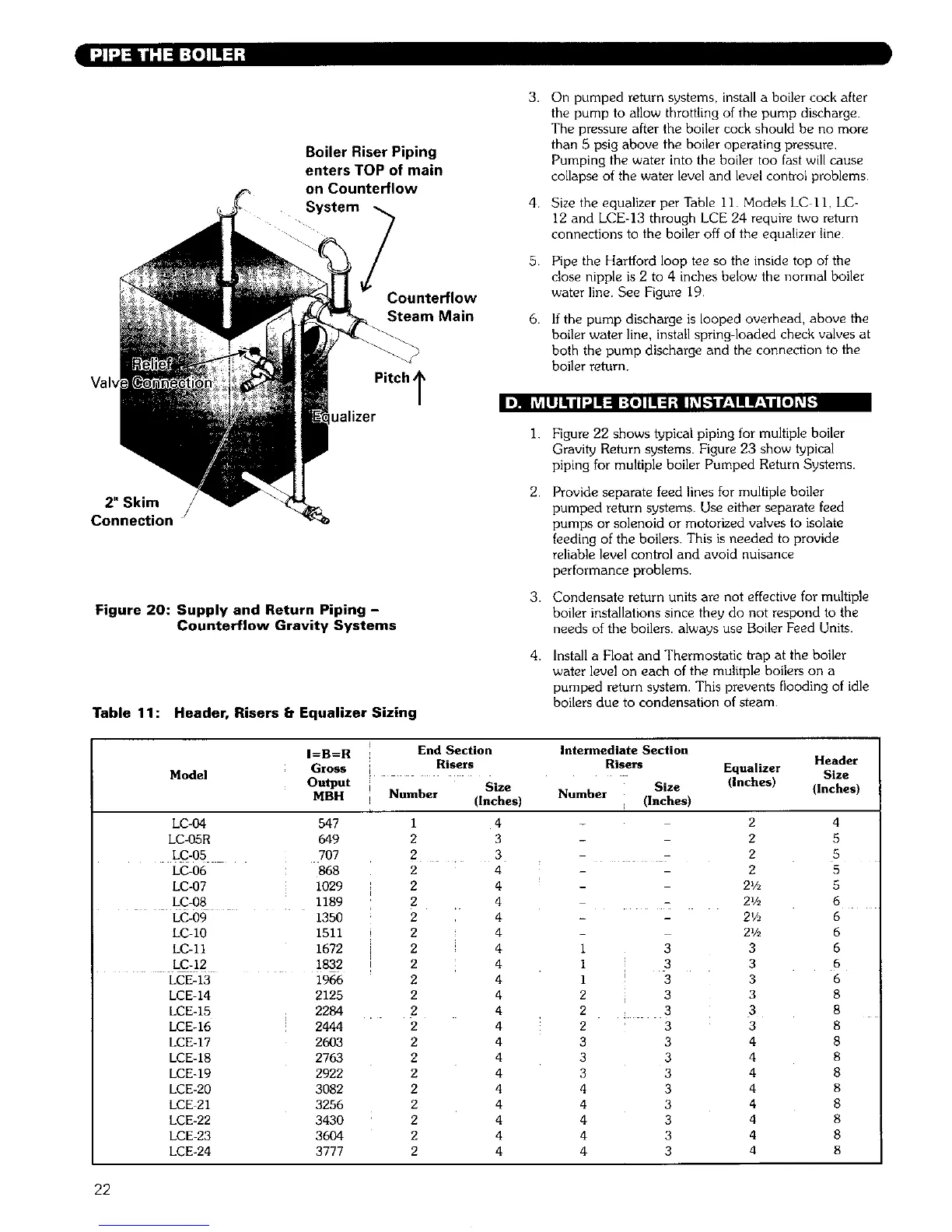
Boiler Riser Piping
enters TOP of main
on Counterflow
System _ 4
Counterflow
Steam Main 6.
I)]q I fldaJallll:J ii=l I:{e] lit :I:llL_LL'tIL,11iW_'_lll[O]t__
2" Skim
Connection
Figure 20: Supply and Return Piping -
Counterflow Gravity Systems
Pitch T
ualizer
On pumped return systems, install a boiler cock after
the pump to allow throttling of the pump discharge.
The pressure after the boiler cock should be no more
than 5 psig above the boiler operating pressure.
Pumping the water into the boiler too fast will cause
collapse of the water level and level control problems.
Size the equalizer per Table 11. Models LC II, LC-
12 and LCE-13 through LCE 24 require two return
connections to the boiler off of the equalizer line.
Pipe the Hartford loop tee so the inside top of the
close nipple is 2 to 4 inches below the normal boiler
water line. See Figure 19.
If the pump discharge is looped overhead, above the
boiler water line, install spring loaded check valves at
both the pump discharge and the connection to the
boiler return.
1.
2.
3.
4.
Figure 22 shows typical piping for multiple boiler
Gravity Return systems. Figure 23 show typical
piping for multiple boiler Pumped Return Systems•
Provide separate feed lines for multiple boiler
pumped return systems. Use either separate feed
pumps or solenoid or motorized valves to isolate
feeding of the boilers. This is needed to provide
reliable level control and avoid nuisance
performance problems.
Condensate return units are not effective for multiple
boiler installations since they do not respond to the
needs of the boilers• always use Boiler Feed Units.
Install a Float and Thermostatic trap at the boiler
water level on each of the mufltple boilers on a
pumped return system• This prevents flooding of idle
boilers due to condensation of steam•
Table 11: Header, Risers r: Equalizer Sizing
I=B=R End Section Intermediate Section
Model Gross !! Risers Risers Equalizer HeaderSize
Output Size Size (inches)
Number (Inches)
MBH Number (Inches) (Inches)
7
LC-04 547
LC-05R 649
LC-05 707
LC-O6 868
LC-O7 1029
LC-08 1189
LC-09 1350
LC-10 1511
LC-11 1672
;
LC-12 1832 !
LCE-13
LCE-14
LCE-15
LCE-16
LCE-17
LCE-18
LCE-19
LCE-20
LCE 21
LCE-22
LCE-23
LCE-24
1966
2125
2284
2444
2603
2763
2922
3082
3256
3430
3604
3777
1 4
2 3
2 3
2 4
2 4
2 4
2 4
2 4
2 4
2 4
2 4
2 4
2 4
2 4
2 4
2 4
2 4
2 4
2 4
2 4
2 4
2 4
2
2
2
2
21/2
2½
21/2
1 3 3
1 3 3
1 3 3
2 3 3
2 _ 3 3
2 3 3
3 3 4
3 3 4
3 3 4
4 3 4
4 3 4
4 3 4
4 3 4
4 3 4
4
5
5
5
5
6
6
6
6
6
6
8
8
8
8
8
8
8
8
8
8
8
22