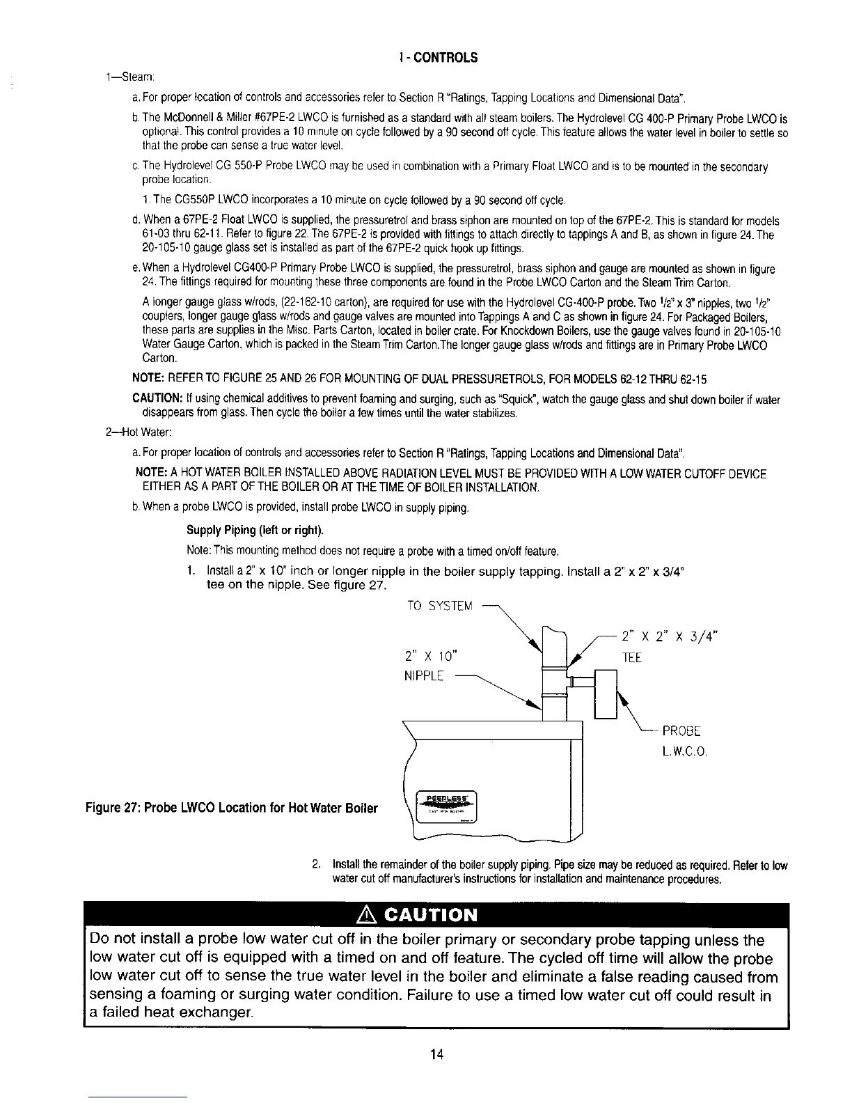
Figure27:ProbeLWCOLocationfor HotWaterBoiler
I - CONTROLS
l--Steam:
a.Forproper}ocationof controlsand accessoriesreferto SectionR "Ratings,TappingLocationsandDimensionalData".
b.TheMcDonnell& Miller#67PE-2LWCOisfurnishedas a standardwith all steamboilers.The HydrolevelCG400-PPrimaryProbeLWCOis
optional.This controlprovidesa lg minuteon cyciefollowedby a 90secondoffcycle.Thisfeatureallowsthe waterlevelinboilerto settleso
that theprobe cansensea truewaterlevel.
c.TheHydrolevelCG550-P ProbeLWCOmaybeusedin combinationwith a PrimaryFloatLWCOand is to bemountedinthe secondary
probe location.
1.TheCG550PLWCOincorporatesa 10minuteon cyclefollowedbya 90secondoff cycle.
d.Whena 67PE-2FloatLWCOis supplied,the pressuretroland brasssiphonare mountedontop ofthe 67PE-2.Thisisstandardformodels
61-03thru 62-1t. Referto figure22.The67PE-2is providedwith fittingsto attachdirectlyto tappingsA and B,as shownin figure24.The
20q 05-10gaugeglassset isinstalledas partof the67PE-2quickhook upfittings.
e.Whena HydrolevelCG400-PPrimaryProbeLWCOis supplied,the pressuretrol,brasssiphonand gaugeare mountedasshowninfigure
24.The fittingsrequiredfor mountingthesethreecomponentsare foundinthe ProbeLWCOCartonand theSteamTrimCarton.
A longergaugeglassw/rods,(22-162-10carton),are requiredfor usewith the HydrolevelCG-400-Pprobe.Two1/2"x 3" nipples,two 1/2"
couplers,longergaugeglassw/rodsand gaugevalvesare mountedintoTappingsA andCas showninfigure24.ForPackagedBoilers,
theseparts are suppliesin the Misc.PartsCarton,locatedin boilercrate.ForKnockdownBoilers,usethegaugevalvesfoundin20-105-10
WaterGaugeCarton,whichis packedin the SteamTrimCarton.Thelongergaugeglassw/rodsandfittingsare in PrimaryProbeLWCO
Carton.
NOTE:REFERTO FIGURE25 AND26 FORMOUNTINGOFDUALPRESSURETROLS,FORMODELS62-12THRU62-15
CAUTION:Ifusingchemicaladditivesto preventfoamingand surging,suchas "Squick",watchthe gaugeglassandshutdownboilerif water
disappearsfrom glass.Thencyclethe boilera fewtimesuntilthe waterstabilizes.
2--Hot Water:
a.Forproperlocationof controlsand accessoriesreferto SectionR "Ratings,TappingLocationsand DimensionalData".
NOTE:A HOTWATERBOILERINSTALLEDABOVERADIATIONLEVELMUSTBEPROVIDEDWITHA LOWWATERCUTOFFDEVICE
EITHERAS A PARTOF THEBOILERORATTHETIMEOFBOILERINSTALLATION.
b.Whena probe LWCOis provided,installprobeLWCOin supplypiping.
Supply Piping (left or right).
Note:This mountingmethoddoesnot requirea probewitha timed on/offfeature.
1. Instal_a 2" x 10" inch or longer nipple in the boiler supply tapping. Install a 2" x 2" x 3/4"
tee on the nipple. See figure 27.
TO SYSTEM
__ 2,,x
2 X 10 ] I,P" TEE
NIPPLE _
RO Eo'
2. Installtheremainderof the boilersupplypiping.Pipesizemaybe reducedasrequired.Referto low
watercut off manufacturer'sinstructionsfor installationandmaintenanceprocedures.
Do not install a probe low water cut off in the boiler primary or secondary probe tapping unless the
low water cut off is equipped with a timed on and off feature. The cycled off time will allow the probe
low water cut off to sense the true water level in the boiler and eliminate a false reading caused from
sensing a foaming or surging water condition. Failure to use a timed low water cut off could result in
a failed heat exchanger.
14