6.
7.
8.
9.
install this boiler so that the gas ignition system
components are protected from water (dripping,
spraying, etc.) during appliance operation and
service (circulator replacement, condensate trap,
control replacements, etc.).
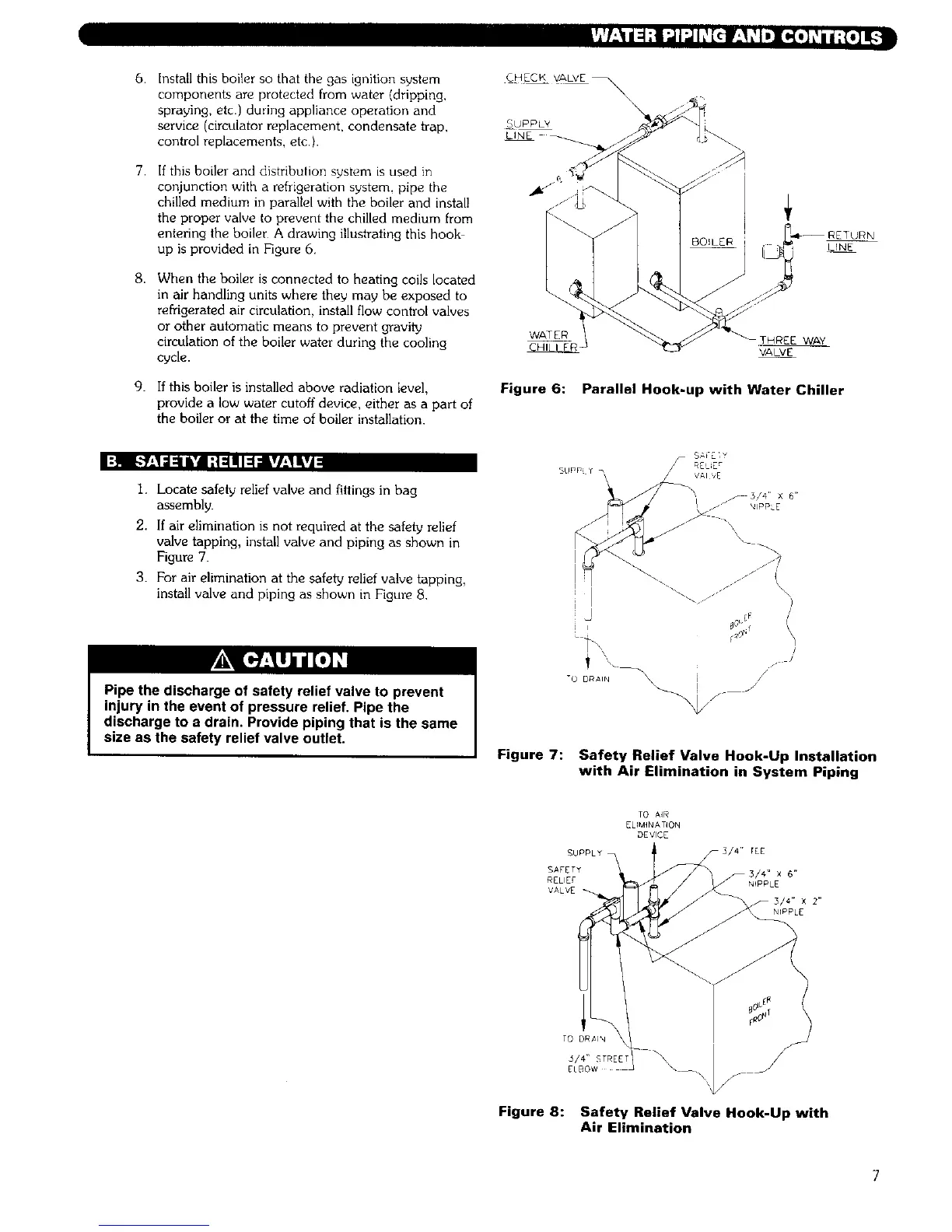
If this boiler and distribution system is used in
conjunction with a refrigeration system, pipe the
chilled medium in parallel with the boiler and install
the proper valve to prevent the chilled medium from
entering the boiler A drawing illustrating this hook
up is provided in Figure 6.
When the boiler is connected to heating coils located
in air handling units where they may be exposed to
refrigerated air circulation, install flow control valves
or other automatic means to prevent gravity
circulation of the boiler water during the cooling
cycle.
If this boiler is installed above radiation level,
provide a low water cutoff device, either as a part of
the boiler or at the time of boiler installation.
CHEEK VALVE _\
\
SUPPLY
LINE
LINE
WATER
[HREE WAY
VALVE
Figure 6: Parallel Hook-up with Water Chiller
I:_II R_,1:1=11&'dI;t :1111I=1;I lVl,_l&vA
1. Locate safety relief valve and fittings in bag
assembly.
2. If air elimination is not required at the safety relief
valve tapping, install valve and piping as shown in
Figure 71
3. For air elimination at the safety relief valve tapping,
install valve and piping as shown in Figure 8.
Pipe the discharge of safety relief valve to prevent
injury in the event of pressure relief. Pipe the
discharge to a drain. Provide piping that is the same
size as the safety relief valve outlet.
I
/./// \\
\
/
/
/
/
Figure 7: Safety Relief Valve Hook-Up Installation
with Air Elimination in System Piping
TO A4R
ELIMINATION
DEVICE
SUPPLY_ F3/4" tEE
SAFETY _3/4" X 6"
RELIE£ NIPPLE
VALVE
TO DRaiN
5/4" _TREET
ELBOW
Figure 8: Safety Relief Valve Hook-Up with
Air Elimination