[o.]NI']l;,ll_[e'li_[_];t,,(o]_l_w]_._k'_J=hVJ_
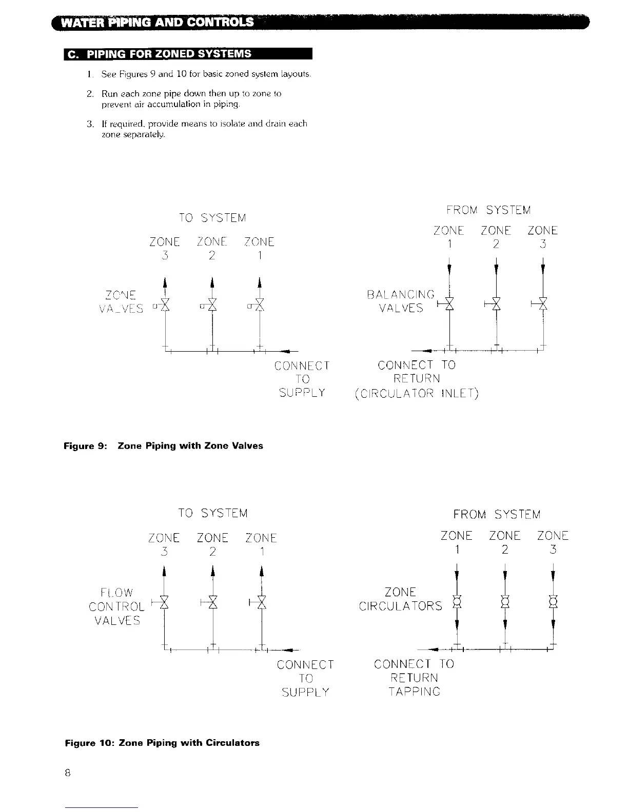
i See Figures 9 and I0 for basic zoned system layouts
2. Run each zone pipe down then up to zone to
prevent air accumulation in piping.
3. If required, provide means to isolate and drain each
zone separately.
TO SYSTEM
ZONE /O'qE
3 2 I
FROM SYSTEM
ZONE ZONE ZONE
1 2 5
Z S NE
'/A ,/E S °S
I
_h
CONNECT
TO
SUPPLY
BALANCING
VALVES
CONNECT TO
RETURN
(CIRCULAIOR INLET)
z
Figure 9: Zone Piping with Zone Valves
TO SYSTEM
ZONE ZONE ZONE
2 1
FROM SYSTEM
ZONE ZONE ZONE
1 2 3
CONTROL
VALVES
L
I
CONNECT
TO
SUPPLY
ZONE
CIRCULATORS
CONNECT TO
RETURN
TAPPING
Figure 10: Zone Piping with Circulators
8