EasyManua.ls Logo

PEERLESS SERIES DE - Electrical; Wiring; Zoned System Wiring; Controls

Default Icon
39 pages
Print Icon
To Next Page IconTo Next Page
To Previous Page IconTo Previous Page
Loading...
Install all electrical wiring in accordance with the National Electrical Code and local requirements.
This unit when installed must be electrically grounded in accordance with the requirements of the authority
having jurisdiction or, in the absence of such requirements, with the current edition of the National Electrical
Code, ANSI/NFPA 70.
h_! i_=_il;]lk_[_
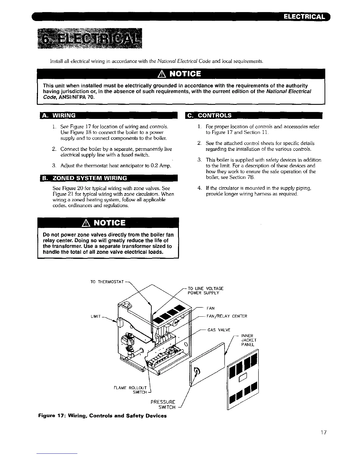
1. SeeFigure 17 forlocation of wiring and controls.
Use Figure 18 to connect the boiler to a power
supply and to connect components to the boiler.
2. Connect the boiler by a separate, permanently live
electrical supply line with a fused switch.
3. Adjust the thermostat heat anticipator to 0.2 Amp.
I;]ii Ir_[e]k_l:=lD]i_"¥*d[-:tll:l_vi|r_li;,llL'![_
See Figure 20 for typical wiring with zone valves. See
Figure 21 for typical wiring with zone circulators. When
wiring a zoned heating system, follow all applicable
codes, ordinances and regulations.
i.
2.
3.
4,
For proper location of controls and accessories refer
to Figure 17 and Section 1i.
See the attached control sheets for specific details
regarding the installation of the various controls.
This boiler is supplied with safety devices in addition
to the limit. For a description of these devices and
how they work to ensure the safe operation of the
boiler, see Section 7B.
If the circulator is mounted in the supply piping,
provide longer wiring harness as required.
TO T
VOLTAGE
POWER SUPPLY
FAN
NTER
VALVE
INNER
JACKET
PANEL
FLAME ROLLOUT
S_TCH-
PRESSURE
SWlTCH
Figure 17: Wiring, Controls and Safety Devices
17

Table of Contents

Related product manuals