3. WATER PIPING AND
L"ll I:[e]ll:l;i [--[IJ'];JIk'dlh_'li_l=] .'|:l/IJ;]_,_
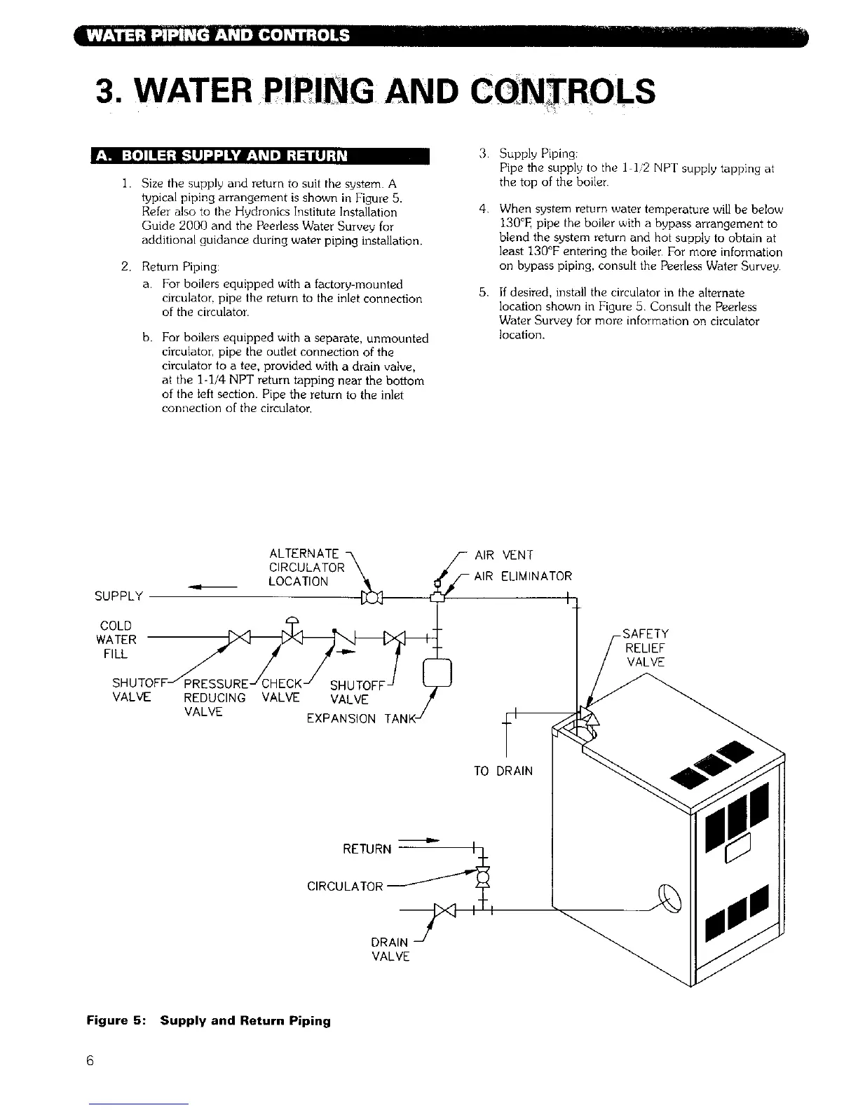
I. Size the supply and return to suit the system. A
typical piping arrangement is shown in Figure 5.
R4er also to the Hydronics Institute Installation
Guide 2000 and the Peerless Water Survey for
additional guidance during water piping installation.
2. Return Piping:
a. For boilers equipped with a factory-mounted
circulator, pipe the return to the inlet connection
of the circulator.
3.
b. For boilers equipped with a separate, unmounted
circulator, pipe the outlet connection of the
circulator to a tee, provided with a drain valve,
at the 1-1/4 NPT return tapping near the bottom
of the left section. Pipe the return to the inlet
connection of the circulator,
4.
5,
Supply Piping:
Pipe the supply to the I ]2 NPT supply tapping at
the top of the boiler
When system return water temperature will be below
130°E pipe the boiler with a bypass arrangement to
blend the system return and hot supply to obtain at
least 130°F entering the boiler For more information
on bypass piping, consult the Peerless Water Survey.
If desired, install the circulator in the alternate
location shown in Figure 5 Consult the Peerless
Water Survey for more information on circulator
location.
SUPPLY
ALTERNATE
CIRCULATOR\
LOCATION
COLD _ .4 N_:_.4 _ , ,.
WATER _
F,LL/- / /-.- ;
SHUTOFFJ PRESSUREJ CHECK J SHUTOFF J
VALVE REDUCING VALVE VALVE
VALVE EXPANSION TANKJ
_- AIR VENT
-AIR ELIMINATOR
RELIEF
VALVE
TO DRAIN
RETURN_/.L_
CIRCULATOR_ y
DRAI:--_ X] III
VALVE
Figure 5: Supply and Return Piping
6