1) _LL _RIN_ _U_T ¢O_pL_ _ APPU^_CE O3OE_ O_DINANC[_ _O REGULAI_ON_
2) I_ ,_Ny O: _E O_qQNAL _£ A_ SUPPLIEO V_ _ _PPUANC£ _$T BE
RE_L_QEO. IT _U_T e_ REPLACED _ Va_ _S _OW_
(_OT}
R_L_Y
¢_L
HI_ W
C_ _ LI_IT
I_NII TM FLAME
_ esR_lttD
-- _20V _IN_ TUBIN¢)
.... 24V _N¢
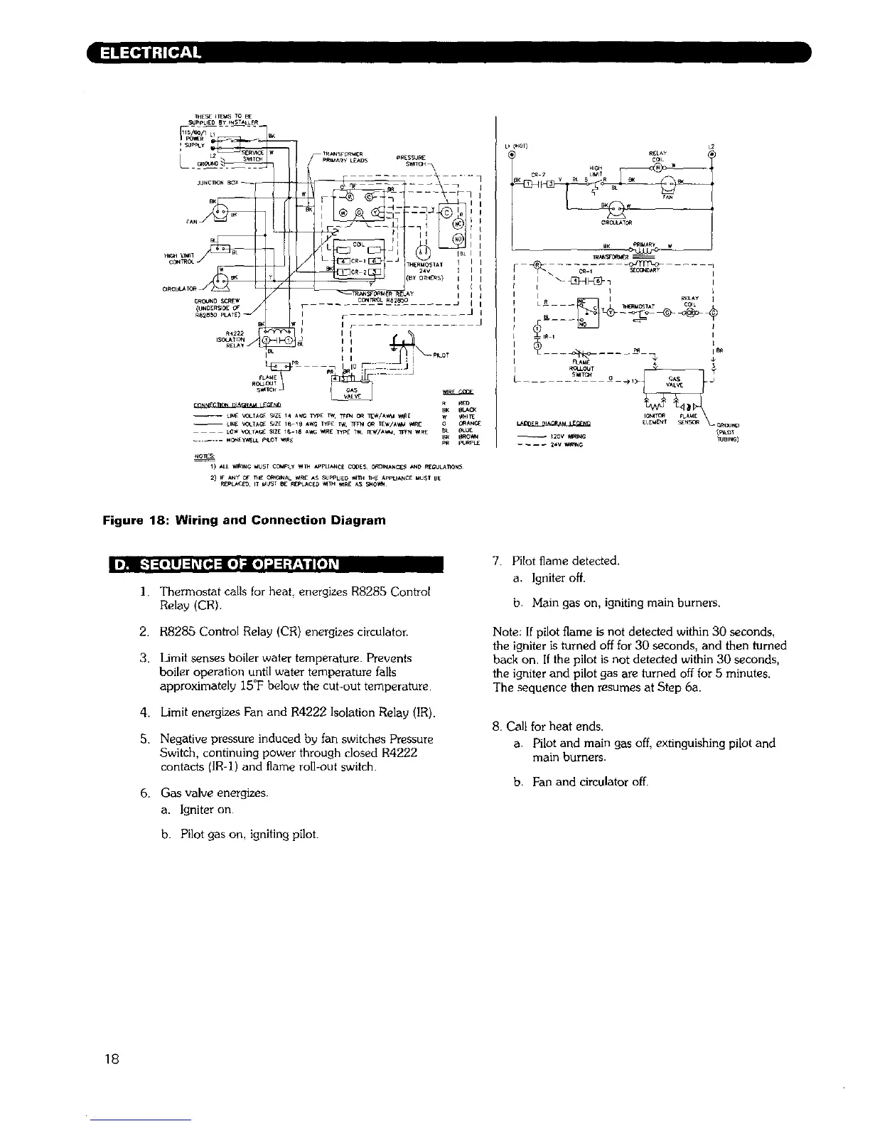
Figure 18: Wiring and Connection Diagram
I _l/.'-] :[o] l J:1_[H :l[o] :lo]':,1:1;_:_1d[_] _
1. Thermostat calls for heal energizes R8285 Control
Relay (CR).
2. R8285 Con_ol Rela_ (CR) energizes circulator.
3. Limit senses boiler water temperature. PreventS
boiler operation until water temperature falls
approximately 15°F below the cut-out temperature.
4. Limit energizes Fan and R4222 Isolation Relay (IR).
5. Negative pressure induced by [an switches Pressure
Switch, continuing power through closed R4222
contacts (IR-I) and flame roll-out switch.
6. Gas valve energizes.
a. Igniter on.
b. Pilot gas on, igniting pilot.
7. Pilot flame detected.
a. Igniter off.
b. Main gas on, igniting main burners.
Note: If pilot flame is not detected within 30 seconds,
the igniter is turned off for 30 seconds, and then turned
back on. If the pilot is not detected within 30 seconds,
the igniter and pilot gas are turned off for 5 minutes.
The sequence then resumes at Step 6a.
8. Call for heat ends.
a. Pilot and main gas off, extinguishing pilot and
main burners.
b. Fan and circulator off.
18