I. Sizeandinstallthegassupplypipingproperlyin
ordertoprovideasupplyofgassufficienttomeet
themaximumdemandwithoutunduelossof
pressure between the meter and the boiler.
2. Determine the volume of gas to be provided to the
boiler in cubic feet per hour. To obtain this value,
divide the Btu per hour rating (on the boiler rating
plate) by the heating value of the gas in Btu per
cubic feet. Obtain the heating value of the gas from
the gas supplien As an alternative, use Table 3 or 4
on the next page to obtain the volume of gas to be
provided to the boiler.
3. Use the value obtained above as the basis for piping
sizing. Size the gas piping in accordance with Table
5. Consult the National Fuel Gas Code for other
sizing options.
4. Locate the drop pipe adjacent to, but not in front of
the boiler.
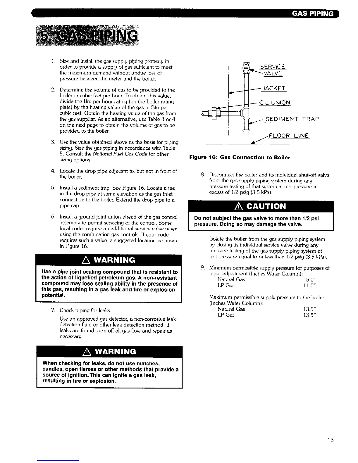
5. Install a sediment trap. See Figure 16. Locate a tee
in the drop pipe at same elevation as the gas inlet
connection to the boilen Extend the drop pipe to a
pipe cap.
6. Install a ground joint union ahead of the gas control
assembly to permit servicing of the control. Some
local codes require an additional service valve when
using the combination gas controls. If your code
requires such a valve, a suggested location is shown
in Figure 16.
Use a pipe joint sealing compound that is resistant to
the action of liquefied petroleum gas. A non-resistant
compound may lose sealing ability in the presence of
this gas, resulting in a gas leak and fire or explosion
potential.
7. Check piping for leaks.
Use an approved gas detector, a non-corrosive leak
detection fluid or other leak detection method. If
leaks are found, turn off all gas flow and repair as
necessa_
I
t
J
i
s Rv C_E
-"-VALVE
.------ dACKET
G.J. UNION
/ SEDIMENT TRAP
/FLOOR LINE
Figure 16: Gas Connection to Boiler
8. Disconnect the boiler and its individual shut-off valve
from the gas supply piping system during any
pressure testing of that system at test pressure in
excess of I/2 psig (3.5 kPa).
Do not subject the gas valve to more than 1/2 psi
pressure. Doing so may damage the valve.
Isolate the boiler from the gas supply piping system
by closing its individuM service valve during any
pressure testing of the gas supply piping system at
test pressure equal to or less than I/2 psig (3,5 kPa).
9. Minimum permissible supply pressure for purposes of
input adjustment (Inches Water Column):
Natural Gas 5.0"
LP Gas 11.0"
Maximum permissible supply pressure to the boiler
(Inches Water Column):
Natural Gas 13.5"
LP Gas 13.5"
When checking for leaks, do not use matches,
candles, open flames or other methods that provide a
source of ignition.This can ignite a gas leak,
resulting in fire or explosion.
15