55
• A DHW call results in the operation of the lead
boiler and its general pump. The DHW pump is
also energized.
• Wiring for a typical circulator zone relay is
shown in Figure 7.4.
4. Setting up Multiple Boiler Operation:
a. Setting the Boiler Address
:
• Press the “Menu” and “Select” keys
simultaneously for 5 seconds to enter the
Installer Menu.
• Find screen #2, Boiler Address. Use the “
M”
key to scroll down to “Burner Settings” on the
menu.
• Pressing “Select” will cause the Boiler Address
value to blink. Use the “
M” or “L” key to
change the value.
• The master boiler will be designated as Boiler
Address: 1.
• All dependent boilers must have sequential boiler
address settings as shown on the following table.
• Once a boiler is designated as a dependent
boiler, the display will show the individual
boiler supply temperature and its status.
• The master boiler will display the system
temperature and the overall status of the
cascade system.
• By pressing the “
M” or “L” key the operator
can view the master boiler status.
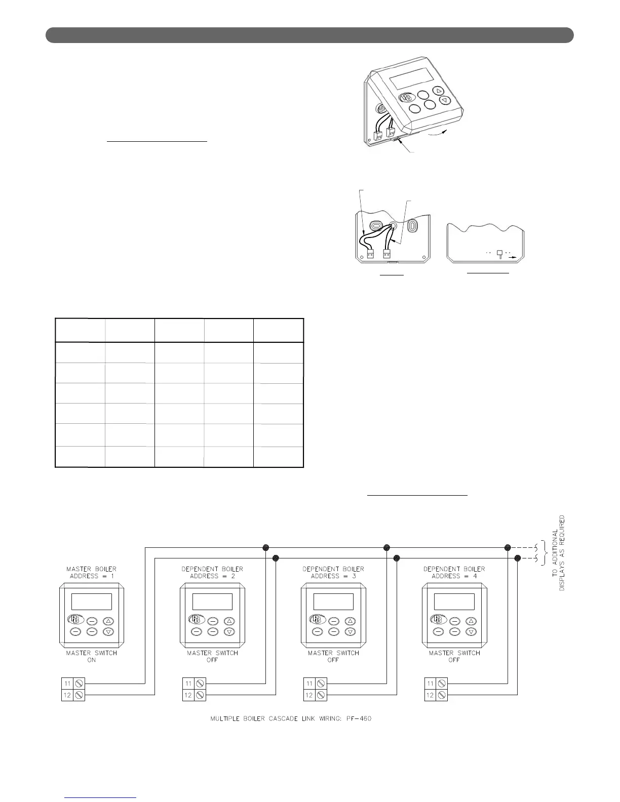
b. Connecting the Cascade Links – PFC-460.
• Re-attach the User Interface Display.
• Connect wires from terminals #11 & #12
between all boilers in the system.
5. Cascade Operation:
a. When a call for Central Heat (CH) or Domestic
Hot Water (DHW) is present, the Master boiler
chooses which boiler will lead based on the
Cascade Rotation Interval
.
Boiler
Operation
Cascade
Address
System
Sensor
Outdoor
Sensor
DHW
Sensor
Stand-alone
Boiler
0
Not
Active
Active
Active
Boiler #1
Master
1
Active
Active
Active
Boiler #2
Dependent
2
Not
Active
Not
Active
Not
Active
Boiler #3
Dependent
3
Not
Active
Not
Active
Not
Active
➞
➞
➞
➞
➞
Boiler #16
Dependent
16
Not
Active
Not
Active
Not
Active
Table 8.33: Cascade Addresses and Sensor Functions
Figure 8.52: Interconnection of Cascade Link Wires