www.pegasustech.com.br 27
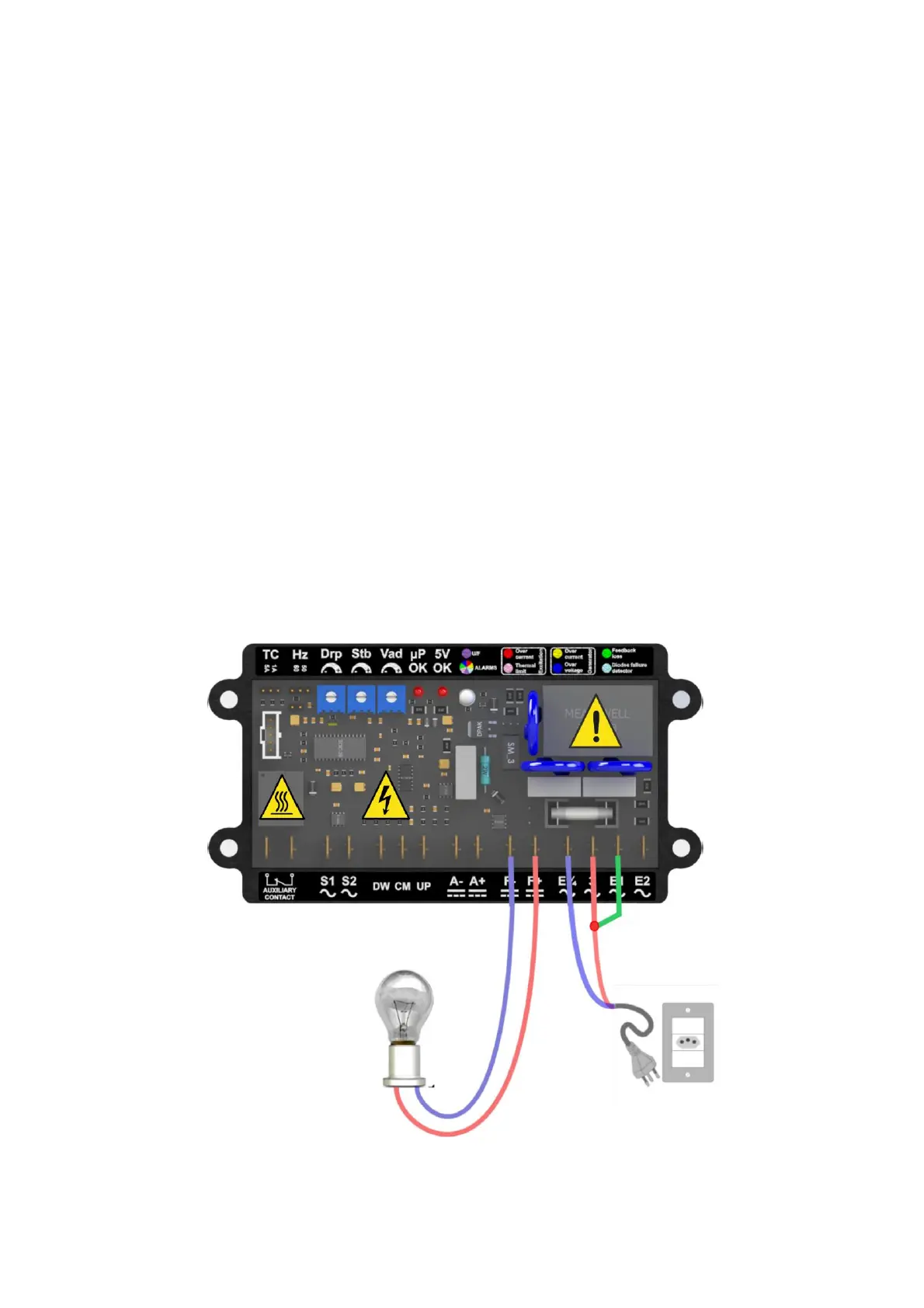
BENCH TEST DIAGRAM
For the bench test connect a lamp at the output of the F + and F- fields, connect at terminals E3 / 4
and 3 to an AC source (between 180 and 220Vac) and make a jumper from connector 3 to connector
E1, as Figure 24.
Set the reference voltage by placing the Vad trimpot in the intermediate position. If the lamp lights
up gradually, turning the trimpot Vad gradually counterclockwise from a certain point the lamp will
gradually reduce the luminous intensity, this is the point where the reference trimpot will be just
below the mains voltage.
If the lamp turns on and off quickly, the Vad trimpot will gradually increase clockwise from a certain
point the lamp will light up gradually, this is where the reference trimpot will be slightly above the
mains voltage.
With the near spot the reference found a setting above this point will light the lamp and a setting
below this point will erase the lamp.
If the ignition occurs as described the regulator is functional.
Return settings to machine specifications.
Note1: If the trimpot is configured far below the AC voltage value, the regulator will activate the
generator overvoltage protection (Blue alarm LED), turning off the excitation.
Note2: When the firing angle reaches its maximum (light on with great intensity) will trigger the
excitation over voltage alarm (Yellow-Green alarm LED).
Note: The peripheral components aren’t supplied with the regulator.