84
EN
Chapter 6 - Debugging instructions
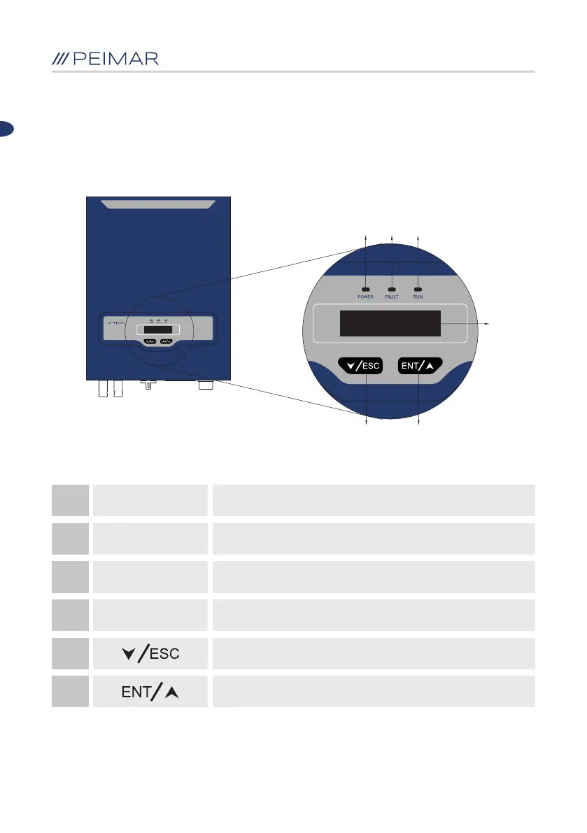
6.1 Introduction of human-computer interface
A
F
B C
D
E
Table 6.1 Instructions of the Interface
A
Yellow LED:
POWER SUPPLY
The yellow light is on when the inverter is powered
Red LED:
ERROR
Green LED:
WORKING
The green light is on during normal operation of the device
B
C
D
E
F
The display shows the operational data, information and
recorded parameters
Button ▼ / Exit
Button ▲ / Enter
The red light goes on when an error occurs
The red light goes off after errors are resolved
DISPLAY
Figure 6.1 Human-computer interface
 Loading...