System 450™ Series Modular Control Systems with Standard Control Modules Technical Bulletin
37
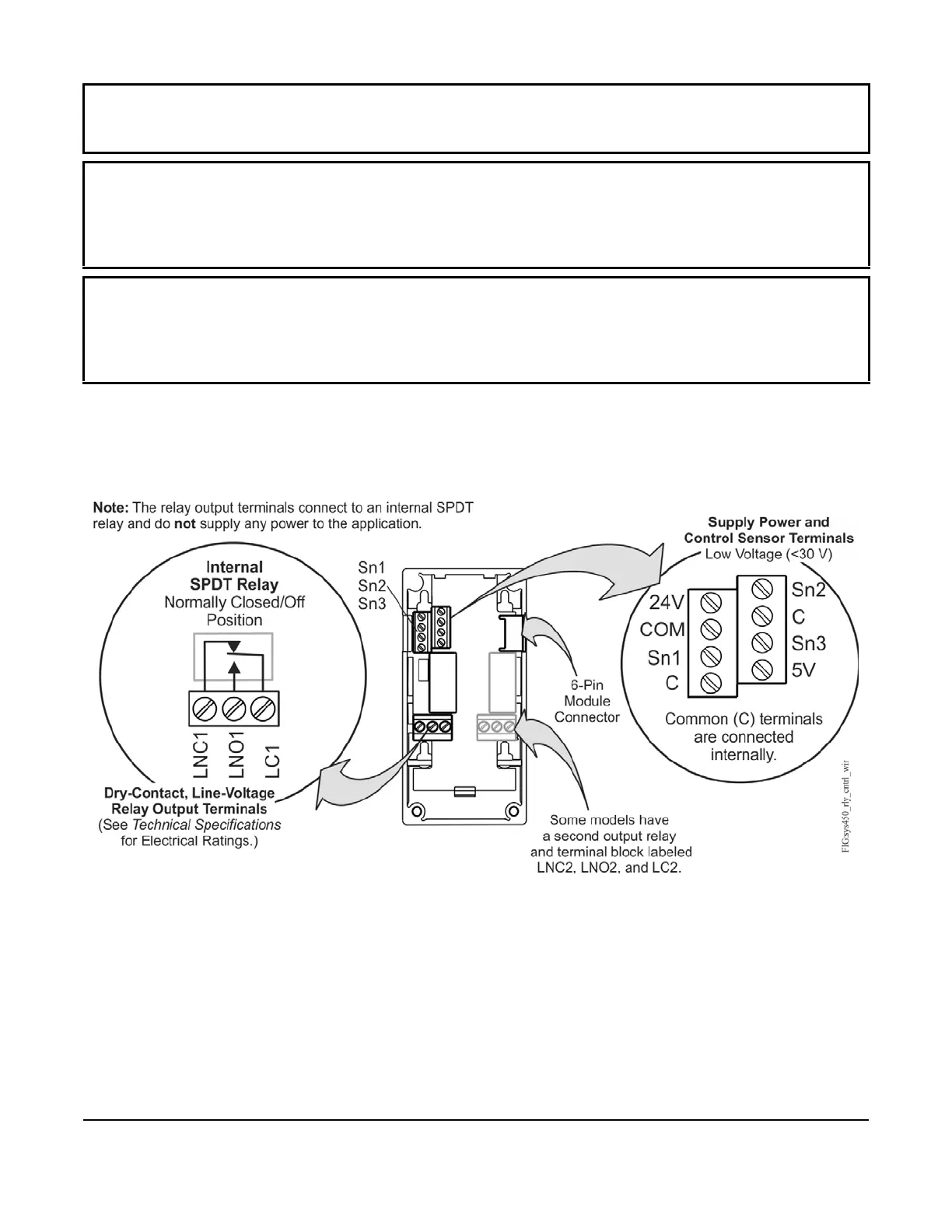
Figure 18 and Figure 19 show the locations of and designations for the wiring terminals for System 450 standard
control modules and expansion modules.
IMPORTANT: Do not connect supply power to the System 450 modules before checking all wiring
connections. Short circuits or improperly connected wires can result in damage to the modules and void any
warranty.
IMPORTANT: A System 450 control module and module assembly can be connected to an internal power
source (a System 450 power module) or an external power source (24 V power connected to the 24V and COM
terminals on the control module), but must not be connected to both power sources simultaneously.
Connecting a control module to both internal and external power sources can damage the modules and void any
warranty.
IMPORTANT: When connecting System 450 compatible sensors with shielded cable to a System 450
control module, connect the cable shield drain lead to one of the C (common) terminals on the input sensor
terminal block. Do not connect the shield at any other point along the cable. Isolate and insulate the shield drain
at the sensor end of the cable. Connecting a cable shield at more than one point can enable transient currents to
flow through the sensor cable shield, which can cause erratic control operation.
Figure 18: Wiring Terminal Details for System 450 Control and
Expansion Modules with Relay Output
 Loading...

