System 450™ Series Modular Control Systems with Standard Control Modules Technical Bulletin
39
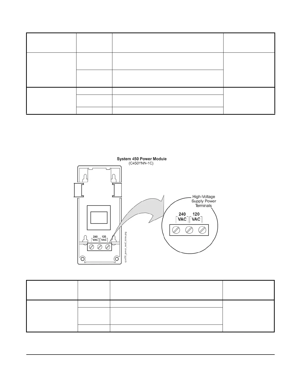
Figure 20 shows the location of and designations for the wiring terminals on a C450YNN-1C
power module. Table 7 provides descriptions, ratings, requirements, and recommended wire sizes for a
C450YNN-1C power module.
Low-Voltage Analog
Output Terminal
Block
(on Control and
Expansion Modules
with Analog Outputs)
AO1
AO2
In conjunction with the COM terminal, provides a
self-detecting analog output signal; either
0 to 10 VDC or 4 to 20 mA.
0.08 mm
2
to 1.5 mm
2
28 AWG to 16 AWG
ACOM In conjunction with the AO1 or AO2 terminal, provides
a self-detecting analog output signal; either 0 to 10
VDC or 4 to 20 mA.
Line-Voltage Supply
Power Terminal
Block (on Power
Modules only)
240 VAC Left terminal is for one 240 VAC supply power lead.
0.34 mm
2
to 2.5 mm
2
22 AWG to 14 AWG
No Label on the
Middle Terminal
Middle terminal is the Common connection for either
the 120 VAC or 240 VAC supply power lead.
120 VAC Right terminal is for one 120 VAC supply power lead.
Table 7: System 450 Power Module Wiring Terminal and Wire Size Information
Terminal Block
Type
(on Module Type)
Terminal
Label
Terminal Function Required Wire
Sizes
Line-Voltage Supply
Power Terminal Block
(on Power Modules)
240 VAC Left terminal is for one 240 VAC supply power lead.
0.34 mm
2
to 2.5 mm
2
22 AWG to 14 AWG
No Label on
the Middle
Terminal
Middle terminal is the Common connection for either
the 120 VAC or 240 VAC supply power lead.
120 VAC Right terminal is for one 120 VAC supply power lead.
Table 6: System 450 Wiring Terminal and Wire Size Information (Part 2 of 2)
Terminal Block
Type
(on Module Type)
Terminal
Label
Terminal Function Required Wire
Sizes
Figure 20: System 450 C450YNN-1C Power Module Showing
High-Voltage Supply Power Terminals
 Loading...

