44404 Rev A
44403 Rev A
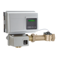
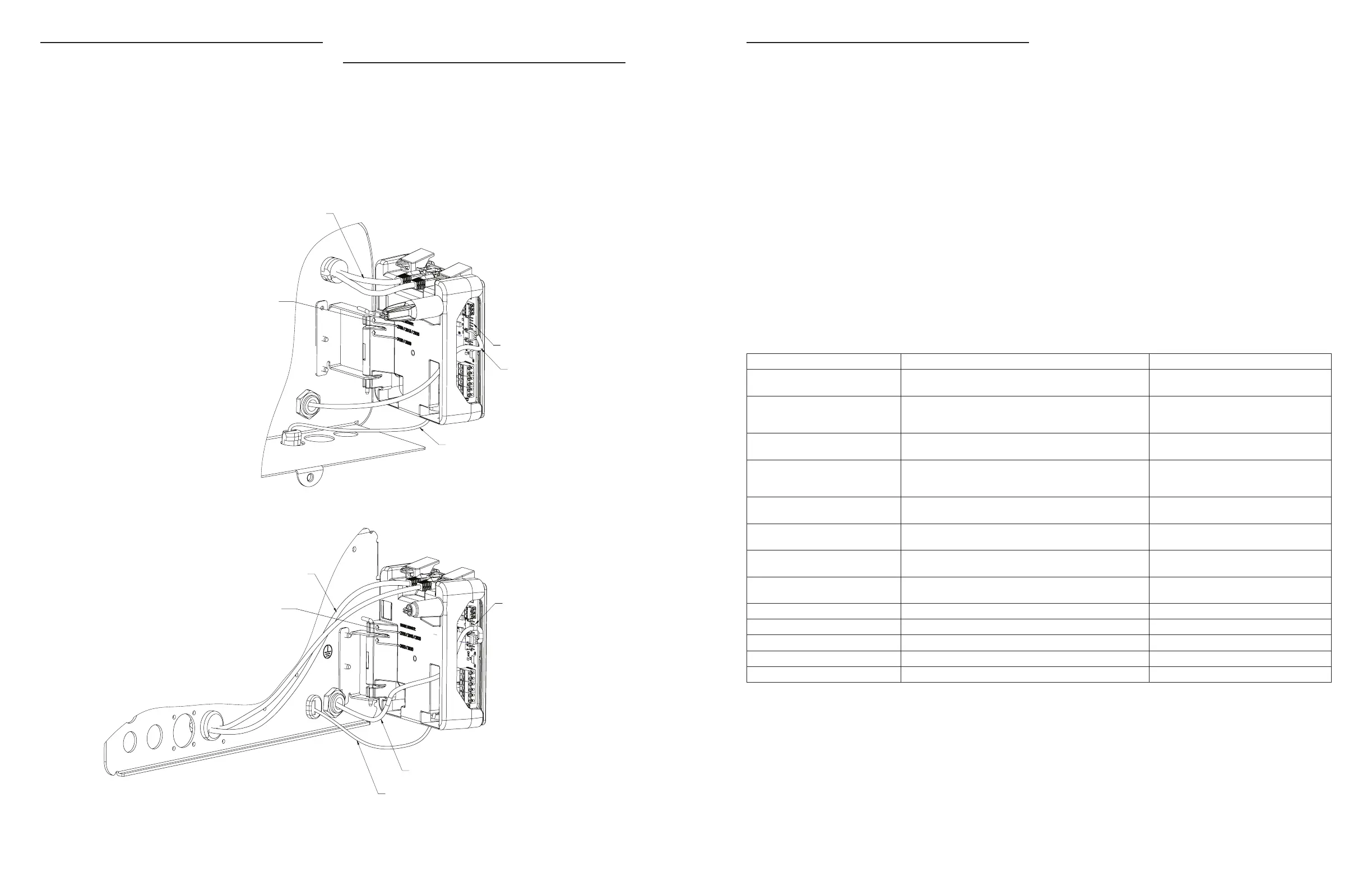
POWER SUPPLY CONNECTIONS
2510/2750/2815/2850/2900 Valves:
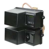
3150/3900 Valves:
Installing the Power Supply:
NOTE: Power Supply includes a harness with 2 black wires
that connect to circuit board, see page 15.
1. Insert black and black transformer wires into 24VDC input
of control.
Communication Cables
Hinge Mount: mount per valve model noted
Meter Cable
Power Supply
Wire Harness
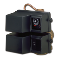
Communication Cables
Power Supply
Meter Cable
Wire Harness
Hinge Mount: mount per valve model noted
NETWORK/COMMUNICATION CABLES
AND CONNECTIONS
Use a shielded CAT5 Network/Communication cable.
Connect the network/communication cable first before
programming.
Cable length between timers/units should not exceed 25 feet.
Connect each unit in series (do not form a loop) together from
one communication port to the next communication port. It
does not matter which one goes to the next one.
ERROR CODES AND TROUBLESHOOTING
Detected Errors
If a communication error is detected, an Error Screen will
appear.
• All units In Service remain in the In Service position.
• All units in Standby go to In Service.
• Any unit in Regeneration when the error occurs
completes Regeneration and goes to In Service.
• No units are allowed to start a Regeneration Cycle while
the error condition exists, unless they are manually forced
into Regeneration.
• When an error is corrected and the error no longer
displays (it may take several seconds for all of the units
in a system to stop displaying the error message), the
system returns to normal operation.
NOTE: During the error condition, the control continues
to monitor the flow meter and update the volume
remaining. Once the error condition is corrected, all
units return to the operating status they were in prior
to the error. Regeneration queue is rebuilt according
to the normal system operation. Or, if more than
one unit has been queued for regeneration, then the
queue is rebuilt according to which one communicates
first.
Message Displayed Cause For Error Correction
Error
Valve Count Mismatch
Number of NXT2 detected does not match selected system
type in Master Programming
Push correct valve settings in Master
Settings
Motor Stall
No Changes Detected in the Optical
Sensor for 6 Seconds
The motor is on but no encoder pulses are detected within a
given duration while homing.
Check the P11 connection and trigger a
manual regeneration.
Motor Run-On
No CAM Switch Change Detected
The motor is on but no encloder pulses are detected or CAM
Switches change state within a given duration.
Verify correct valve type is chosen. Trigger a
manual regeneration.
Optical Sensor
Undesired change detected by the
Optical Sensor
The motor is off but additional encoder pulses are detected. Trigger a manual regeneration.
Over-Current
Motor Over-Current is Detected
Motor current exceeds thresholds. Trigger a manual regeneration.
Flow Meter Error
Continuous Flow Detected
Flow exceeded specified threshold for a specific duration. Trigger a manual regeneration.
Error
Send/Receive Failure
During a setting push, a packet was missing.
Reconnect communication cables and push
setting in Master Settings.
Error
System Type Mismatch on Network
The system type among connected units does not match.
Push correct system settings in Master
Settings.
Microcontroller Error Calibration or manufacturing test was not performed Contact your Pentair representative.
100 Days Without Regen 100 Days have expired without a regeneration Trigger a manual regeneration
18 • Pentair Fleck NXT2 Timer Pentair Fleck NXT2 Timer • 19
 Loading...