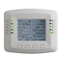
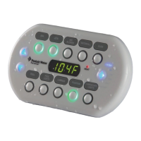
SPACOMMAND
®
Spa-Side Remote Installation and User’s Guide
20
Connecting the SpaCommand
®
Spa-Side Remote to a CP3xxx load
center using adapter
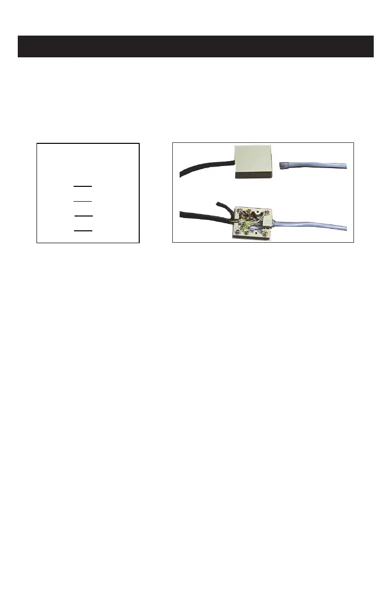
Strip back the cable one inch and ends of leads ¼-inch. Open the cable adapter (P/N
520000, included in kit). Insert the spa-side remote cable into the adapter and attach
wires to the terminals (see the wiring diagram below). Attach the six conductor flat cable
pig-tail between cable adapter and the COM port connector on the circuit board in the
Compool load center.
Upgrading from the Compool System SS8 to the SpaCommand
Spa-Side Remote
The spa-side remote may be used to replace the SS8 spa-side remote on the CP3xxx
family of systems. Note: The spa-side remote can still only control up to eight functions.
Note: The SS8 must also have been plumbed with a minimum one inch conduit.
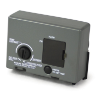
Remove SS8 Remote
Unplug the SS8 from the load center then pull out the unit from spa-side location.
Remove the SS8 mounting bracket from spa-side location (two screws). All that should
be left is a minimum of one inch. diameter conduit.
Install the SpaCommand Spa-Side Remote
For spa-side remote installation instructions, see page 8-9).
IMPORTANT NOTE: INTELLIFLO
®
PUMP SPEED CONTROL
For Compool systems: In order for SpaCommand remote to control the IntelliFlo pump
speed, the pump must be connected via an RS-485 communication cable to the COM
port on the Compool system circuit board.
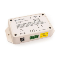
Controller Adapter
RED YEL
YEL RED
GRN GRN
BLK WHT
WIRING
Spa-Side Remote Wiring
Diagram
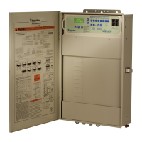
Compool system connector block with
cables
COMPOOL
®
CONTROL SYSTEMS SS8 REMOTE UPGRADE INSTALLATION
 Loading...