5
INTELLIFLO3™ VSF / INTELLIPRO3™ VSF Variable Speed and Flow Pump Installation and Maintenance Guide
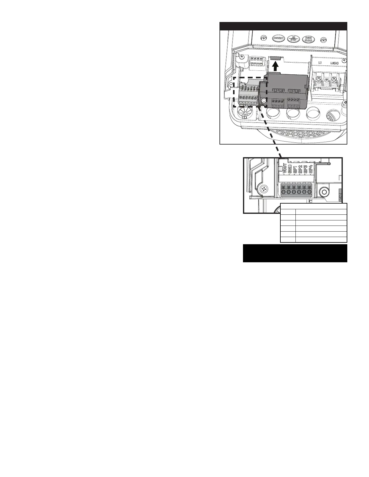
Relay Control Board Digital Inputs
If the optional Relay Control Board Kit (P/N 356365z) is installed,
the board's digital inputs can be connected to an automation
system in order to control four customizable speed or ow
programs.
Note: If multiple external input triggers are received,
programs will follow the following priority:
PROGRAM 4 > 3 > 2 > 1.
Note: If the pump has been stopped via the ON/STOP button
(ON/STOP LED is solid red), ON/STOP must be pressed again
before the pump will operate.
When a low voltage signal is received by a control board digital
input, the pump will run the program set to that specic digital
input. This digital input program will override any scheduled
programs, automation or manual input.
Note: Refer to the Pentair Home User's Guide (P/N 356088) for
instructions on viewing and editing the pump programs.
Note: Refer to the Relay Control Board Installation Guide (P/N
356994) for instructions on installing the control board.
The Relay Control Board also provides a +12V Output Signal
(marked VOUT) that can be used to trigger its own Digital Inputs.
This output signal is the recommended input for Speed Digital
Inputs.
The output signal will need to be switched via an External Control
(i.e. automation relay, external system component switch) to
activate the desired speed program.
PROGRAM 4 > 3 > 2 > 1
Note: This VOUT output signal is output from the drive
ONLY and should never be wired to a voltage supply!
VOUT
OUTPUT FOR D.I. TRIGGER (+12V)
SP4
SPEED 4 DIGITAL INPUT (5-24V AC/DC)
SP1
SPEED 1 DIGITAL INPUT (5-24V AC/DC)
SP2
SPEED 2 DIGITAL INPUT (5-24V AC/DC)
SP3
SPEED 3 DIGITAL INPUT (5-24V AC/DC)
GND
GROUND
DIGITAL INPUT WIRING
DIGITAL INPUTS
(Low Voltage)
RELAY CONTROL BOARD
 Loading...