23
INTELLIFLOXF
®
and INTELLIPROXF
®
VSF Variable Speed and Flow Pump Installation and User’s Guide
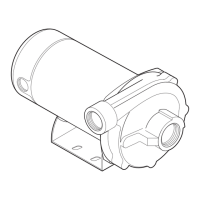
Pump Reassembly / Seal Replacement
1. When installing the replacement mechanical seal, use silicone sealant on the metal portion before
pressing into the seal plate.
Note: Use extreme care when applying sealant. Be sure no sealant contacts the seal plate surface or the
ceramic seal. Allow sealant to cure overnight before reassembling.
2. Before installing the rotating portion of the seal onto the impeller, be sure the impeller is clean. Use a light
density soap and water to lubricate the inside of the seal. Press the ceramic seal into the seal plate with
your thumbs and wipe off the ceramic and carbon faces with a clean cloth.
3. Remount the seal plate to the motor using the four (4) lock washers and four (4) nuts.
4. At the back of the motor, hold the motor shaft in place using a 1/4-inch hex key wrench. Firmly tighten the
impeller clockwise onto the motor shaft to 40 in-lbs.
5. Ensure the lock washer is in place on the impeller set screw and firmly tighten the set screw counter-
clockwise to 78.5 in-lbs.
Note: Some pumps contain an o-ring instead of a lock washer. Before reassembling, inspect the o-ring for
damage or cracks and replace if needed.
6. Remount the diffuser onto the seal plate using the three (3) diffuser screws. Ensure the plastic pins and
holding screw inserts are aligned (see “TOP” indicator).
Note: Ensure that the seal plate o-ring is clean and free of debris.
7. Grease the diffuser o-ring and seal plate gasket prior to reassembly.
8. Assemble the motor subassembly to the housing. Do not tighten the nuts and washers until all four (4)
motor bolts are in place. Using a torque wrench, install and tighten the four nuts to a torque value of 100
in-lbs (maximum). Do not overtighten the nuts.
Note: Ensure that the seal plate gasket is properly seated inside of the pump assembly. The seal
gasket can be pinched between the seal plate and the pump housing while tightening these six (6) nuts,
preventing a proper seal and producing a slow leak when the pump is restarted.
9. Reinstall the drive onto the motor.
10. Reinstall the two (2) drain plugs and fill the pump with water.
11. Reinstall the pump lid/locking ring. Refer to page 21, Cleaning the Pump Strainer Basket.
12. Reconnect the RS-485 communication cable to the pump
13. Prime the system. Refer to page 5, Priming the Pump.
The pump impeller may have sharp edges that could potentially cut or scratch the user's hands. Pentair recommends that
safety gloves be worn when holding the impeller during disassembly and reassembly.
STRAINER BASKET
LID O-RING
VOLUTE
DRAIN PLUG
O-RING (2X)
DIFFUSER O-RING
DIFFUSER SCREWS (3X)
DIFFUSER
IMPELLER SET SCREW
AND WASHER
IMPELLER
SEAL PLATE O-RING
SEAL PLATE
FOOT
FOOT INSERT
WASHER (6X)
LOCK WASHER (10X)
ACORN NUTS (10X)
MOTOR
DRIVE
DRIVE KEYPAD COVER
DRIVE TO MOTOR
SCREWS (3X)
KEYPAD RELOCATION
DRIVE GASKET
MOTOR PADS (3X)
DRIVE COVER
MECHANICAL SEAL
Pump Illustrated Parts View
 Loading...