VBP-HH1-V3.0*
Product Description
2013-06
11
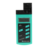
Address and data display
Depending on the operating mode, two digits and the letters A and B are used to
display various information in this area of the display.
■ The address of the currently selected AS-Interface node differs according
to the AS-Interface specification supported and the address areas
Sta ndard (shown without letters), A and B.
■ Target address which is to be communicated to the currently selected AS-
Interface node
■ Display of read data
■ Display of data to be written
Address field
All the AS-Interface nodes of the AS-Interface network are shown in this area of
the display:
■ If the addressing device detects AS-Interface nodes from various address
areas, the various address areas are identified in the right-hand section of
the address field, as follows:
• Without letters: For AS-Interface nodes that do not support the AS-
Interface specification 2.1.
• A: For AS-Interface nodes belonging to address area A.
• B: For AS-Interface nodes belonging to address area B.
The display of the detected addresses in the respective address area
changes every 2 seconds.
■ The addresses of all AS-Interface nodes currently connected to the
addressing device are shown in the Addressing operating mode by
flashing digits. In all other operating modes, the addresses of the AS-
Interface nodes shown flashing are those being actively accessed.
■ During Addressing, the non-flashing digits represent addresses of AS-
Interface nodes that have been assigned addresses by the addressing
device.
Operating mode display
The current operating mode is shown in this area of the display.
 Loading...