2013-06
12
VBP-HH1-V3.0*
Product Description
4.4.3 Button assignment
4.4.4 Button combinations
4.4.5 Connections
The addressing device uses the following connections:
■ Connection socket for the power supply to charge the internal battery on
the underside of the addressing device.
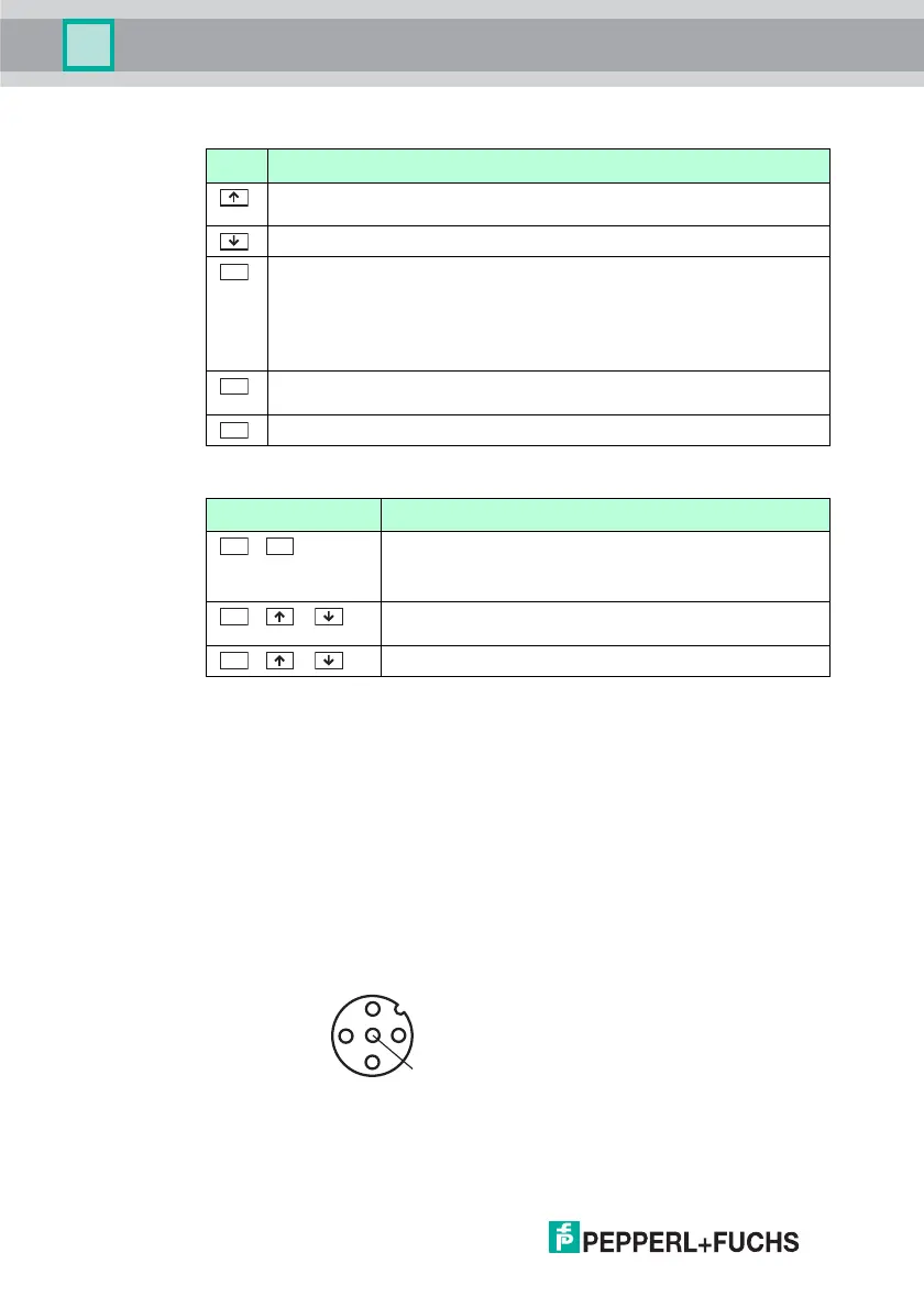
■ M12 socket on the AS-Interface connection adapter with the following
pinning:
• Pin 1: AS-Interface+
• Pin 2: Digital input for optical addressing adapter
• Pin 3: AS-Interface-
• Pin 4: Digital output for optical addressing adapter
• Pin 5: Power supply for optical addressing adapter
■ Several individual AS-Interface+/- sockets on the AS-Interface connection
adapter for connection of AS-Interface nodes.
Button Description
Set values (e.g.slave address, ID1 data, slave parameters, slave data), change of
operating mode
Set values (e.g. slave address, ID1 data, slave parameters, slave data)
The function depends on the operating mode:
■ transfer of a new slave address to the slave (ADDR)
■ transfer of ID1 data (ID1)
■ transfer of slave parameters (PARA)
■ transfer of slave data (DATA)
Switch on addressing device, search and read out slave addresses
Double click: switch off addressing device
Change between operating modes
PRG
MODE
Butto n combinations Descript ion
&
Function dependent on the duration of pressing:
■ Short press: address 0 is assigned to the connected slave
■ Long press: the list of assigned slaves is deleted
& or
Navigate through source addresses of several slaves connected
to the addressing device
& or
Navigate through the operating modes
ADR
MODE