24
PERI Design Tables
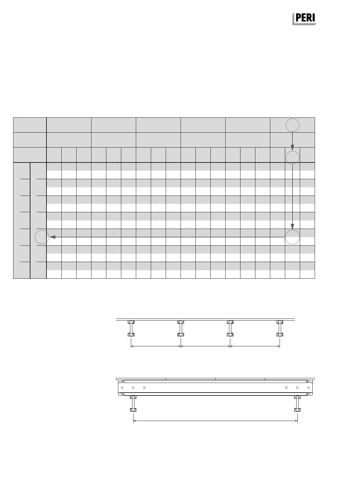
Example: dimensioning with VT 20/
VT 20 girder combination
Formlining
The 3-S sheet, 21 mm, has been taken
into consideration. Values for other
sheets: see PERI Tables.
1. Secondary girder spacing a
Support of the formlining is subject to
the slab thickness and the type of
formlining used.
(Fig. A8.02).
Secondary girder spacing 62.5 cm
2. Main girder spacing b
Support for the cross beam.
Permissible span for cross beam
according to PERI Tables: 2.05 m.
Selected: 2.00 m, depending on the
spatial geometry.
(Fig. A8.03)
Main girder spacing 2.00 m
Fig. A8.02
a = 62.5
Slab thickness: d = 20 cm
h = 2.80 m
VT 20
21 mm,
62.5 x 250 cm
Clear height:
Main and cross beam:
Plywood:
a = 62.5 a = 62.5
b = 2.05 m
Fig. A8.03
Fig. A8.01
0.10 0.12 0.14 0.16 0.18 0.20
4.4 4.8 5.3 5.8 6.3 6.8
0.75 0.625 0.50 0.75 0.625 0.50 0.75 0.625 0.50 0.75 0.625 0.50 0.75 0.625 0.50 0.75 0.625 0.50
0.25 0.50
3.21 3.41 3.67 3.04 3.23 3.48 2.91 3.09 3.33 2.79 2.97 3.20 2.70 2.86 3.09 2.61 2.77 2.99
7.3 7.8 8.4 7.7 8.2 8.9 8.1 8.6 9.3 8.5 9.1 9.8 8.9 9.5 10.2 9.3 9.9 10.7
0.375 0.75
3.21 3.41 3.67 3.04 3.23 3.48 2.91 3.09 3.33 2.79 2.97 3.20 2.70 2.86 3.09 2.61 2.77 2.99
11.0 11.7 12.6 11.6 12.3 13.3 12.2 13.0 14.0 12.8 13.6 14.7 13.4 14.2 15.3 14.0 14.9 16.0
0.50 1.00
3.21 3.41 3.67 3.04 3.23 3.48 2.91 3.09 3.33 2.79 2.97 3.20 2.70 2.86 3.09 2.61 2.77 2.99
14.7 15.6 16.8 15.5 16.4 17.7 16.3 17.3 18.6 17.1 18.1 19.5 17.9 19.0 20.4 18.6 19.8 21.3
0.50 1.25
3.21 3.41 3.67 3.04 3.23 3.46 2.91 3.09 3.14 2.79 2.88 2.88 2.66 2.66 2.66 2.46 2.46 2.46
18.3 19.5 21.0 19.3 20.5 22.0 20.3 21.6 22.0 21.3 22.0 22.0 22.0 22.0 22.0 22.0 22.0 22.0
0.50 1.50
3.21 3.21 3.21 2.89 2.89 2.89 2.62 2.62 2.62 2.40 2.40 2.40 2.21 2.21 2.21 2.05 2.05 2.05
22.0 22.0 22.0 22.0 22.0 22.0 22.0 22.0 22.0 22.0 22.0 22.0 22.0 22.0 22.0 22.0 22.0 22.0
0.50 1.75
2.75 2.75 2.75 2.47 2.47 2.47 2.25 2.25 2.25 2.06 2.06 2.06 1.90 1.90 1.90 1.76 1.76 1.76
22.0 22.0 22.0 22.0 22.0 22.0 22.0 22.0 22.0 22.0 22.0 22.0 22.0 22.0 22.0 22.0 22.0 22.0
0.50 2.00
2.41 2.41 2.41 2.16 2.16 2.16 1.97 1.97 1.97 1.80 1.80 1.80 1.66 1.66 1.66 1.54 1.54 1.54
22.0 22.0 22.0 22.0 22.0 22.0 22.0 22.0 22.0 22.0 22.0 22.0 22.0 22.0 22.0 22.0 22.0 22.0
Prop spacing c [m]
Cantilever e [m]
Slab Thickness
d [m]
Load q*
[kN/m²]
Secondary girder
spacing a [m]
MULTIFLEX Girder Slab Formwork
Assembly Instructions for Standard Configuration
A8 Dimensioning of the Slab Formwork