46
0.30 0.40 0.50 0.60 0.70 0.80
1
1 x GT 24
2
2 x VT 20
1
1 x GT 24
2
2 x VT 20
1
2 x GT 24
2
2 x VT 20
1
2 x GT 24
2
2 x VT 20
1
2 x GT 24
2
3 x VT 20
1
2 x GT 24
2
3 x VT 20
0 2.01 4.21 1.74 3.59 1.57 3.14 1.45 2.80 1.36 2.60 *1.29 *1.85
0.20 2.05 4.56 1.91 3.30 1.77 2.69 1.64 1.95 *1.35 *1.42 *1.02 *1.07
0.25 1.83 4.00 1.71 2.51 1.62 2.36 1.55 1.77 *1.23 *1.29 *0.94 *0.98
0.30 1.77 3.58 1.66 2.34 1.58 2.10 1.51 1.61 *1.13 *1.19 *0.86 *0.90
0.35 1.71 3.30 1.62 2.06 1.54 1.88 1.40 1.45 *1.04 *1.09 *0.77 *0.83
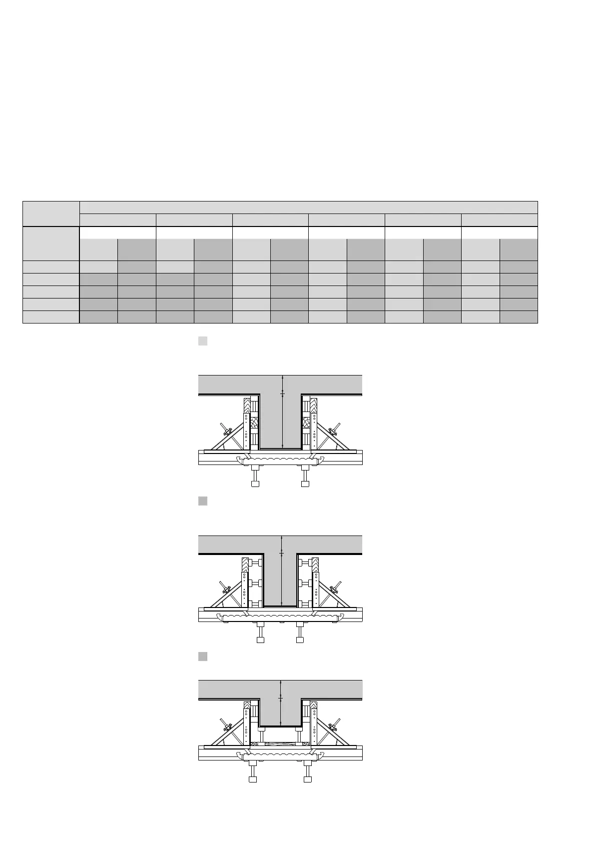
Beams
Beam Formwork UZ
Permissible width of influence [m] for
UZ Beam Bracket 40 depending on the
beam depth and slab thickness
d = Slab Thickness
h = Beam Depth
The max. deflection is l/500
*) vertical timber in the UZ Beam Bracket 40
10 x 8 cm! (instead of 8 x 8 cm)
The above values relate to the load-
bearing capacity of the UZ Beam
Bracket 40, the vertical 8 x 8 cm timber
and the secondary beams as they are
shown on the drawings.
Depending on the formlining used,
additional secondary beams may be
needed.
Separate structural calculations must
be provided to show that the sub-struc-
ture can carry all resulting loads.
The equivalent load (V/100) acting
horizontally and the pressures arising
on one side (e.g. the edge beam) are to
be accommodated by suitable means
provided by the contractor.
Side form with 1 or 2 GT 24 girders
(vertical)
dh
Side form with 2 or 3 VT 20 girders
(horizontal)
dh
Packing of the beam soffit form
dh
Version 1:
Version 2:
Version 3:
Slab
Thickness
d [m]
Beam Depth h [m]
VersionVersionVersionVersionVersionVersion