47
0.20 0.25 0.30 0.35
0 3.27 3.27 3.27 3.27 2.82 2.86 2.86 2.86 1.63 2.60 2.60 2.60 0.97 2.21 1.69 1.90
0.20 1.19 2.75 2.05 1.88 0.71 1.64 1.24 1.32 0.45 1.02 0.79 0.99 - 0.69 0.54 0.76
0.25 1.07 2.46 1.84 1.63 0.61 1.39 1.06 1.16 0.39 0.88 0.68 0.87 - 0.60 0.47 0.67
0.30 0.93 2.15 1.61 1.43 0.54 1.23 0.94 1.03 - 0.77 0.60 0.78 - 0.53 0.41 0.60
0.35 0.82 1.89 1.41 1.28 0.47 1.08 0.83 0.92 - 0.69 0.53 0.69 - 0.47 - 0.54
0.40 0.73 1.69 1.26 1.14 0.42 0.96 0.73 0.83 - 0.62 0.48 0.63 - 0.42 - 0.49
0.40 0.50 0.60
0 0.62 1.41 1.09 1.40 - 0.68 0.53 0.83 - - - 0.54
0.20 - 0.49 - 0.60 - - - 0.40 ----
0.25 - 0.43 - 0.53 --------
0.30 - - - 0.48 --------
0.35 - - - 0.44 --------
0.40 - - - 0.40 --------
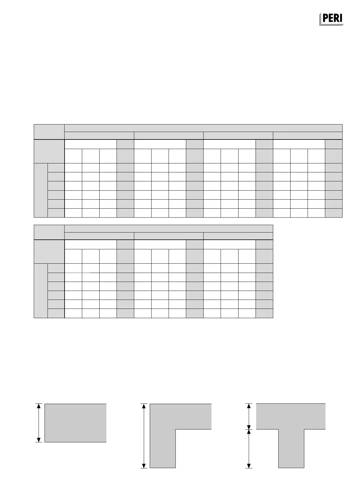
Beams
Stopend Angle AW
Permissible width of influence [m]
for Stopend Angle AW depending
on the slab thickness, beam depth
and type of fixing
– nail with 8 nails Ø 3.1 mm
(6 at the front and 2 at the back)
* Using the Guardrail Post AW on
SKYDECL panels is not permissible.
1. Stopend for Slab Formwork
dh
h
h
2. Slab with Edge Beam 3. Slab with T-Beam
Separate structural calculations must
be provided to show that the sub-struc-
ture can carry all resulting loads. The
equivalent load (V/100) acting horizon-
tally and the pressures arising on one
side (e.g. the edge beam) are to be
accommodated by suitable means
provided by the contractor.
Height of Side Formwork h [m]
Sub-
Structure
Slab Thickness d [m]
Height of Side Formwork h [m]
Sub-
Structure
Slab Thickness d [m]
nailed to clamping nailed to clamping nailed to clamping nailed to clamping
Formlining
21 mm
Timber
Girder
Timber
Girder
Formlining
21 mm
Timber
Girder
Timber
Girder
Formlining
21 mm
Timber
Girder
Timber
Girder
Formlining
21 mm
Timber
Girder
Timber
Girder
nailed to clamping nailed to clamping nailed to clamping
Formlining
21 mm
Timber
Girder
Timber
Girder
Formlining
21 mm
Timber
Girder
Timber
Girder
Formlining
21 mm
Timber
Girder
Timber
Girder
SKYDECK*
SKYDECK* SKYDECK* SKYDECK*
SKYDECK* SKYDECK* SKYDECK*