09931228D
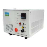
Rear View of Peltier Controller
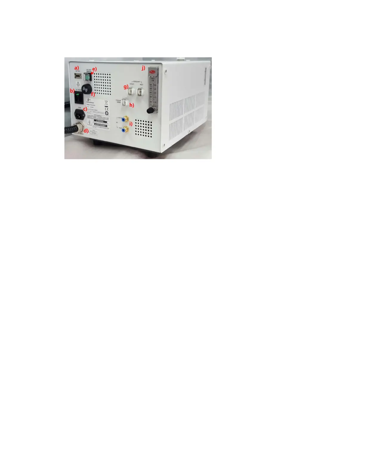
Figure 4 Rear view of the Peltier Controller
a. RS-232 port
b. AC POWER: Main Power ON/OFF
c. Fuse: AC socket + Fuse Holder
d. Interface: Interface cable for connecting with Peltier controlled Single Cell
e. Air Vent Manual button: Used for removing the air in the coolant hose.
f. Buzzer: It makes an alarm sound. If there is any problem before the measurement, the
buzzer beeps 6 times at every 10 sec. If the malfunction occurs during the operation, the
buzzer beeps twice at every 10 sec.
g. Quick Coupler of Coolant lnlet/Outlet
h. Quick Coupler of Coolant Drain
i. N
2
Gas Inlet/Outlet ports
NOTE:
N
2
gas is not always required [Tube for N
2
gas is not supplied with the accessory].
j. Flow Gauge: Indicator of the flow rate of N
2
gas.
Configuration of the equipment
Peltier controlled Single Cell
Peltier Controller
Power Cord, 3ea
Interface Cable (RS-232 and USB to RS-232), 1each
Coolant, 2ea
Coolant Hose, 1ea
Magnetic Stirrer, 1ea