E. Disconnect the coupler (10) terminal stopper
from
the plate complete.
F
Loosen the M4 screw (12) and remove the
clamp.
G. Remove the M4 screw
(13).
H. Pull out the stator complete (4) from the coil
plate
(3).
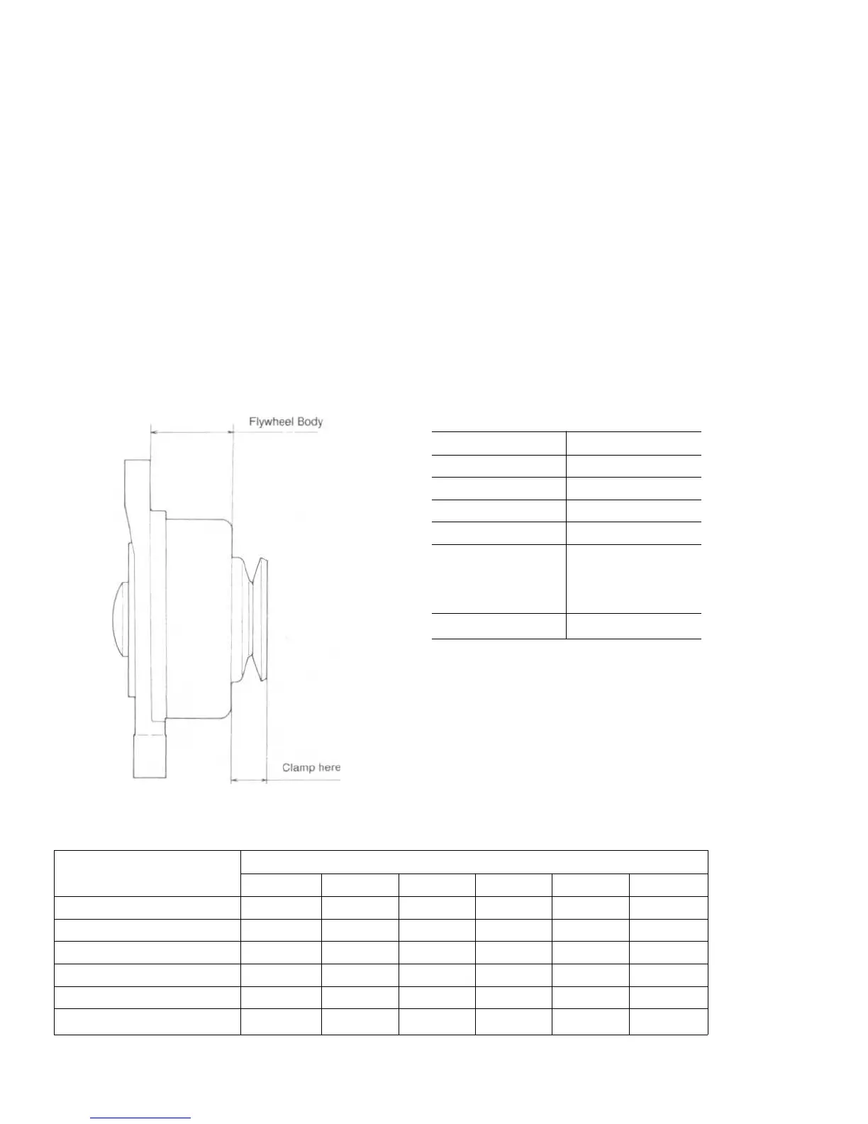
I. Position the coil plate (3) rear side on a surface
plate, and insert a rod having diameter of
approximately 24mm. Then push the bearing
with a press to remove. (Replace the front
bearing as a flywheel complete).
NOTE: NEVER CLAMP the flywheel body with
any vice.
J.
Rotate the bearing manually to confirm that it
rotates without noise.
-
Reassembly
A. Reassemble the alternator in the reverse of
order
of its disassembly, paying attention to the
following precautions.
a. When installing
the bearing,
place the
bearing
housing side of the coil plate (3) on
the flat
plate. Then press the bearing from
rear side of
the coil plate using a rod of 31 mm
diameter. (
Apply a rod on the outer face of
the bearing.
)
b. Tighten the nut (7) with the torque of 2.5 to
3.Okgf.m.
c. Clamp the flywheel complete.
d. Never suspend the alternator from a lead
wire.
Regulator
-
Specification
Type
RS5101
Part No.
185516060
Weight
Approx. 250 gram
Applicable battery
12V
Charging lamp
12V less than 3.4W
Applicable alternator
No-load voltage of less
than 70V
Output current of less
than 16A
Adjusted voltage
14.5+0.5V
Inspection
A. Adjusted voltage
Refer to "Inspection of Alternator".
B. Unit inspection of regulator
With circuit tester, carry out the inspection as
shown in the separate table.
E0107
RS5101 Tester Checking table.
Tester (+) terminal
Colour of cable
Tester
(-)
termina
Blue Blue
Red
Yellow
Green
Black
Blue
OFF
ON
OFF OFF OFF
Blue
OFF
ON
OFF OFF OFF
Red
OFF OFF OFF OFF OFF
Yellow
ON ON ON
OFF
ON
Green
OFF OFF OFF OFF OFF
Black
OFF OFF OFF OFF OFF
 Loading...