SEBU8121 15
Product Information Section
Model Views
i02247483
Engine Description
The Perkins110
4 Electronic Engine is designed for
the following applications: machine and industrial
mobile equipment. The engines are available in the
following typ
es of aspiration:
•
Turbocharged aftercooled
•
Turbocharged
•
Naturally asp
irated
Engine Specif
ications
Note: The front end of the engine is opposite the
flywheel end
of the engine. The left and the right
sides of the engine are determined from the flywheel
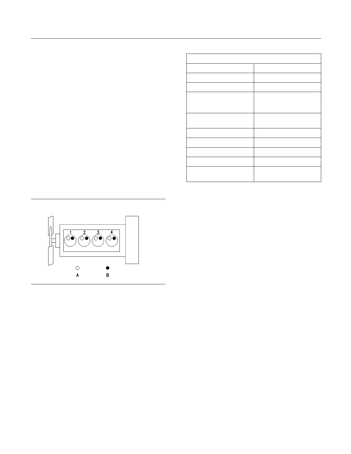
end. The number 1 cylinder is the front cylinder.
g00984281
Illustration 10
Typical example
1104 Electronic engine
(A) Inlet valves
(B) Exhaust v alves
Table 1
1104 Electronic Engine Specifications
Number of Cylinders 4 In-Line
Bore
105 mm (4.134 inch)
Stroke 127 mm (5.0 inch)
Aspiration
Turbocharged, aftercooled
Turbocharged
Naturall y aspirated
Compression
Ratio
NA 19.25:1 NA
T 18.23:1 T, TA
Displacement
4.4L(268in
3
)
Firing Order 1-3-4-2
Rotation (flywheel end) Counterclockwise
Valve Lash Setting (Inlet) 0.20 mm (0.008 inch)
Valve Lash Setting
(Exhaust)
0.45 mm (0.018 inch)
E
lectronic Engine Features
The Perkins 1104 Electronic Engine is designed with
e
lectronic controls. The integral on board computer
controls the operation of the engine. Current
operating conditions are monitored. The Electronic
Control Module (ECM) controls the response of the
engine to these conditions and to the demands of the
operator. These conditions and operator demands
determine the precise control of fuel injection by the
ECM. The electronic engine control system provides
the following features:
•
Engine monitoring
•
Engine speed governing
•
Cold start strategy
•
Automatic air/fuel ratio control
•
Torque rise shaping
•
Automatic altitude compensation
•
Fuel temperature compensation
•
Injection timing control
•
System diagnostics
For more information on electronic engine features,
refer to the Operation and Maintenance Manual,
“Features and Controls” topic (Operation Section).