1
18 User’s Handbook, TSL 4186E, Issue 2
4012/16 Diesel
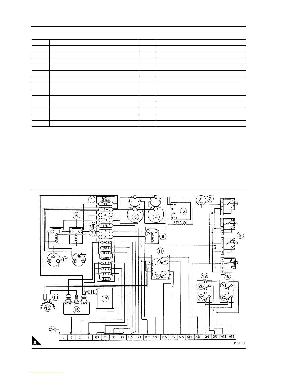
4016 engine wiring diagram (twin starters and electronic governor)
(1) To operate only in conjunction with overspeed fault.
Notes:
z All switches are shown with the engine at rest.
z The diagram refers to standard engine wiring on engines fitted with a terminal box.
Item Description Item Description
A1 Engine fitted terminal box A13 Overspeed
A2 Oil pressure switch A14 Magnetic pick-ups
A3 Starter motor 1 A15 Engine flywheel
A4 Starter motor 2 A16 Electronic governor control box
A5 Battery charging alternator A17 Electronic governor actuator
A6 Start inhibit relays A18 ‘A' bank engine fault switches
A7 Emergency stop switch A19 'B' bank engine fault switches
A8 Starter relay A20 Water temperature
A9
Four air shutoff solenoid valves energise to stop
(1)
. Must be manually reset after operating
A21 Water temperature
A22 Oil pressure
A10 Fuel stop solenoids energised to run A23 Oil pressure
A11 Two switch speed unit A24 Typical linking box to controller
A12 Speed ref.