174 KENR9126
Troubleshooting Section
g01803553
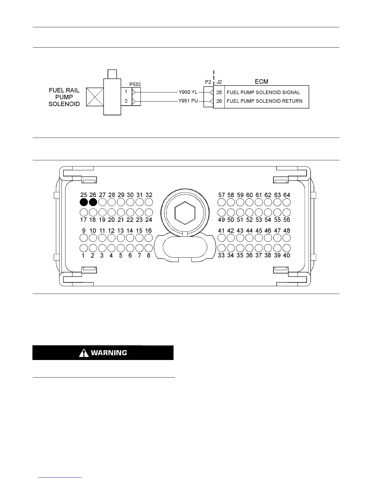
Illustration 68
Typical sch ematic of the circuit for the fuel rail pum p solenoid
g01803554
Illustration 69
Typical view of the P2 pin loc ations for the electrical power su pply circuit
(25) Fuel rail pum p solenoid PWM signal (26) Fuel rail pump solenoid return
Test Step 1. Inspect the Electrical
Connectors and the Harness
Electrical shock hazard. The fuel rail pump sole-
noid uses 6 3 to 73 volts.
A. Turn the keyswitch to the OFF position.
B. Thoroughly inspect the harness connector
P2/J2 and the suspect connector P532. Refer to
Troubleshooting, “Electrical Connectors - Inspect”
for details.
C. Perform a 45 N (10 lb) pull test on each of the
wires in the solenoid connector P532 and the
connector pins 25 and 26 that are associated with
the fuel rail pump solenoid. Refer to illustration 69.
D. Check the harness for abrasions and for pinch
points from the battery to the ECM. Check the
harness for abrasions and for pinch points from
the key switch to the ECM.
E. Perform a “Wiggle Test” by using the electronic
service tool in order to identify intermittent
connections.
Expected Result:
All connectors, pins, and sockets are completely
coupled and/or inserted. The harness is free of
corrosion, of abrasion, and of pinch points.
Results:
•
OK – The connectors and the harness appear to
be OK. Proceed to Test Step 2.