PAL-AT Installation Manual
16
mounting height of the PAL-AT panel.
2.9 Impedance Jumper Setting
Refer to figures 2-2 and 2-3 for positioning the impedance jumper. The 2-pin jumper is placed in position
A, B, C, or D according to the type of cable and whether a Zener Barrier Assembly (for hazardous
locations) is connected to the selected cable. The position should be:
Jumper Position Cable Type Zener Barrier Ass’y Installed
A ATP only No
B ATP only N/A
C All others No
D All others Yes
2.10 UL
PAL-AT is listed by Underwriters Laboratories, Inc. for installation in ordinary locations. The optional Zener
Barrier Panel must be installed if any leak detection circuits are located in hazardous locations.
CAUTION - The maximum operating voltage allowed in the PAL-AT panel is 250 VAC. In
addition, the voltage on any wires to the control relays must be limited to 250 VAC.
2.11 FCC and CE Compliance Requirements
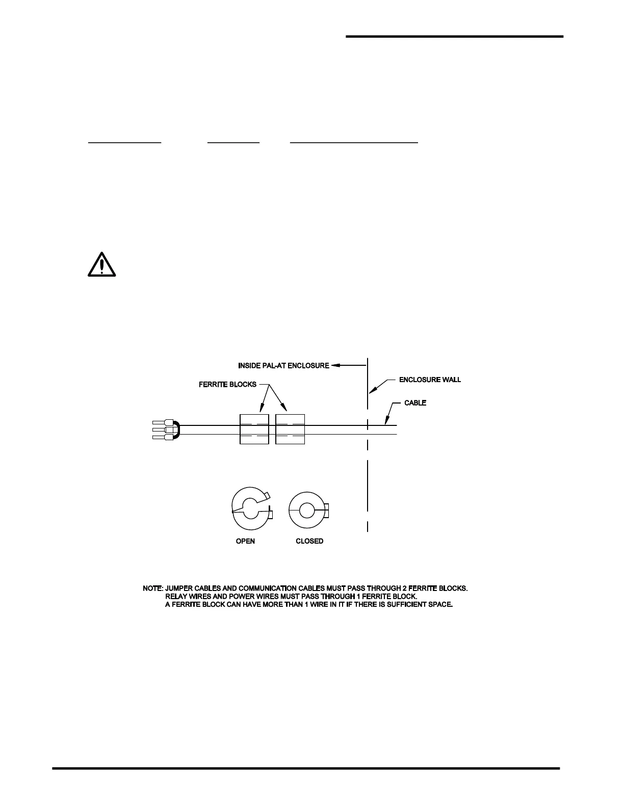
Each PAL-AT system is supplied with several "ferrite blocks" (PermAlert part # 8058207) to comply with
FCC and CE regulations for a Class A digital device. The sensor cables, jumper cables, and all
communications wires must pass through two blocks before exiting the enclosure (see figure 2-4). All
relay wires and power wires must pass through one block.
Figure 2-4
Ferrite Block Assembly
 Loading...
