PAL-AT Installation Manual
55
8.4.3 Alternative System Test
1. Connect the entire cable string to the PAL-AT panel.
2. Make sure the panel is turned off. Set the impedance jumper for the cable under test – position C (w/o
ZBA) or D (w/ZBA). If applicable, make sure the replaceable fuse in the ZBP is good.
3. Measure the resistance at the far end of the cable string. Connect one test lead to the center contact
of the last connector and the other lead to the connector body. The resistance should be less than 60
ohms + 10 ohms/1000' [75 ohms/300 m] of cable string.
4. If intermittent connections are suspected, gently flex the connectors while the meter is monitored.
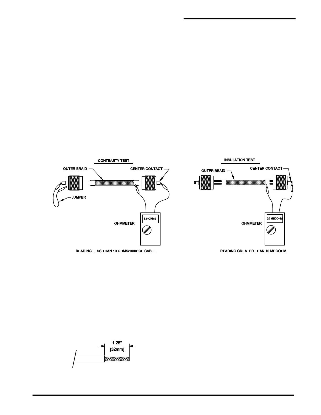
8.4.4 Insulation Test
The insulation test checks for a short between the center conductor and outer braid.
1. Remove the jumper wire used in the continuity test, as shown in figure 8-1 and connect one ohmmeter
test lead to the connector's center contact and the other lead to the connector body.
2. A good cable will give a full-scale reading (at least 10 megohms). Test readings below full scale
indicate damaged cable or an improperly installed connector. If you cannot resolve the problem,
contact PermAlert's Field Service Department for assistance.
Figure 8-1
Cable Test Procedures
8.5 Cable Connections to Panels
8.5.1 General
The ends of the jumper cables connected to the PAL-AT panel or Zener Barrier Panel need to be
terminated with wire ferrules. The ferrules provide a positive connection and prevent stray strands of the
wires from shorting to adjacent terminals.
8.5.2 Ferrule Installation in PAL-AT Panel
Step A Remove 1.25” [32 mm] of cable jacket
Step B Separate the braid wire into two equal groups. It is easier to unbraid the wire if it is done in ¼”
long increments. It is helpful when working with JMP-U cable to keep tools and fingers damp when
 Loading...
