PAL-AT Installation Manual
57
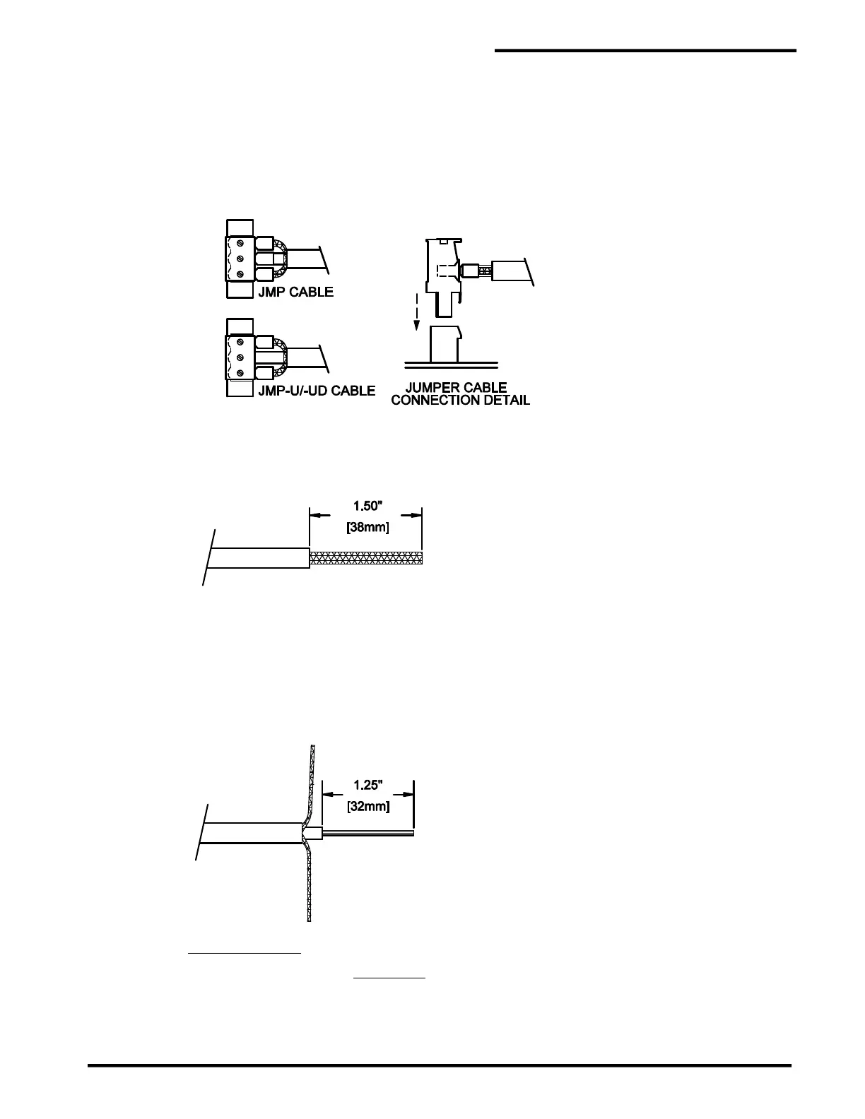
Step E The cable ferrules should be inserted into the cable plug and tightened as shown. Before
connecting the cable, route the excess cable in the enclosure so there will not be
excessive strain or twisting at the terminals. Insert the plug into the appropriate receptacle
as shown. The center conductor ferrule should be in the center terminal of the plug and the two
braid ferrules in the outer terminals. When removing the cable, grip the plug and pull it straight
out of the receptacle. Note the plug and receptacle are polarized so they can only be
connected one way.
8.5.3 Ferrule Installation in Zener Barrier Panel
Step A Remove 1.5” [38 mm] of cable jacket.
Step B Separate the braid wire into two equal groups. Twist each group into a small wire. Remove 1.25”
[32 mm] of insulation from the center wire.
Step C JMP-U/-UD Cable
Slide a 14 AWG [2.5 mm²] uninsulated ferrule onto the center wire until it is tight against the center
insulation. Crimp the ferrule using a 2.5 mm² die. Then crimp it again with a 1.5 mm die. Slide a
16 AWG [1.5 mm²] insulated ferrule over each group of braid wire twisted strands. Align the ferrule
ends as shown while minimizing slack in the braid wire. Crimp the ferrules using a 1.0 mm crimp
die.
 Loading...
