PAL-AT Installation Manual
75
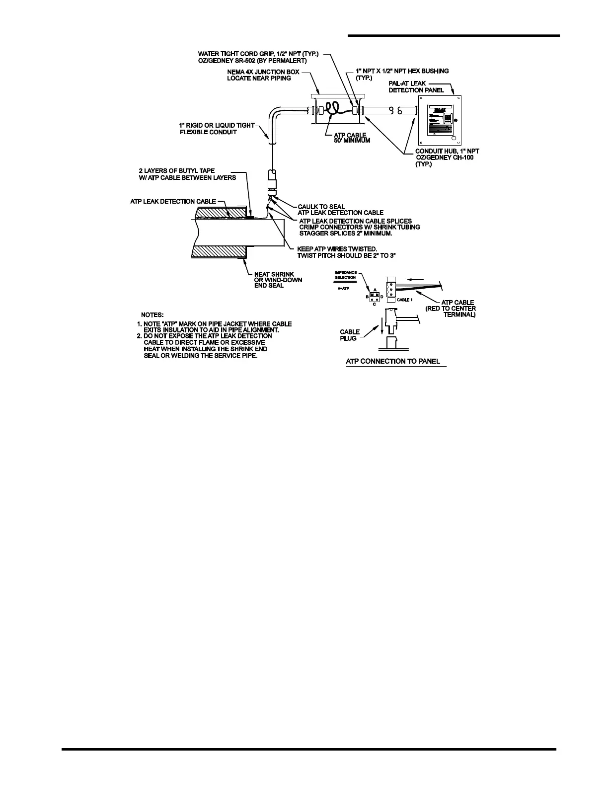
Figure 10-1
ATP Cable Connection - Start of Run
10.7 ATP Cable Splices
The ATP cable is spliced at field joints with crimp connectors using the following steps (see figure 10-2).
1. The red wires should be spliced on one side of the pipe joint and the white wires on the other side,
each splice approximately 3"- 4" [75 mm -100 mm] from the end of the pipe.
2. If the ATP cable from the first pipe is not directly in line with the cable from the second pipe, the cable
should be routed in as direct a line as possible between the two splice points (refer to Branch Return
design in figure 10-2).
3. Cut the red wire from one pipe so the end is centered over the first splice location. Cut the other red
wire so the wires meet. Minimize excess slack in the wire.
4. Strip 5/16"-3/8" [7 mm - 9 mm] of insulation from the ends of the red wires. The wire size is 1.5 mm
2
(metric size). If the correct stripping tool, Model T60/124, part number 8068309, is not available, use
a tool for #14 AWG. Do not use a smaller die or uncalibrated hand tool, such as wire cutters, that
may damage the conductor.
5. Slide a 1½” [38 mm] long piece of adhesive lined shrink tubing on the wire before crimping
the connector.
6. The crimp tool, Model T60/125, part number 8068308, is ratcheted so the crimp must be completed
once it is started. The crimp connector has an indentation (wire stop) in the center. Two crimps are
required, one on each half of the connector. The model T60/125 crimp tool must be used.
7. Insert one red wire into the connector and place the connector in the T60/125 tool so the die is
centered over the half of the connector with the wire. Make sure the wire is fully inserted into the
connector until it hits the stop, and then crimp the connector.
8. Repeat step 7 with the other red wire.
 Loading...
