EasyManuals Logo

Permalert PAL-AT AT30K Installation Manual

Default Icon
84 pages
To Next Page IconTo Next Page
To Previous Page IconTo Previous Page
Page #70 background imageLoading...
Page #70 background image
PAL-AT Installation Manual
70
9.6 Probe Tests
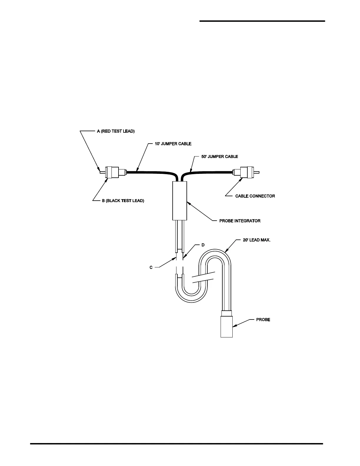
Figure 9-9 shows a typical probe integrator test setup. There are four test procedures based on the type
of integrator used. The red lead of an ohmmeter should be connected to the center pin of either of the
connectors (point A). The black lead should be connected to the connector housing (point B). The
ohmmeter should be set to resistance. Follow the test procedure in figure 9-10 to test the probe integrator
and probes.
Figure 9-9
Probe Integrator Test Setup

Table of Contents

Other manuals for Permalert PAL-AT AT30K

Questions and Answers:

Question and Answer IconNeed help?

Do you have a question about the Permalert PAL-AT AT30K and is the answer not in the manual?

Permalert PAL-AT AT30K Specifications

General IconGeneral
BrandPermalert
ModelPAL-AT AT30K
CategoryMeasuring Instruments
LanguageEnglish

Related product manuals