PAL-AT Installation Manual
56
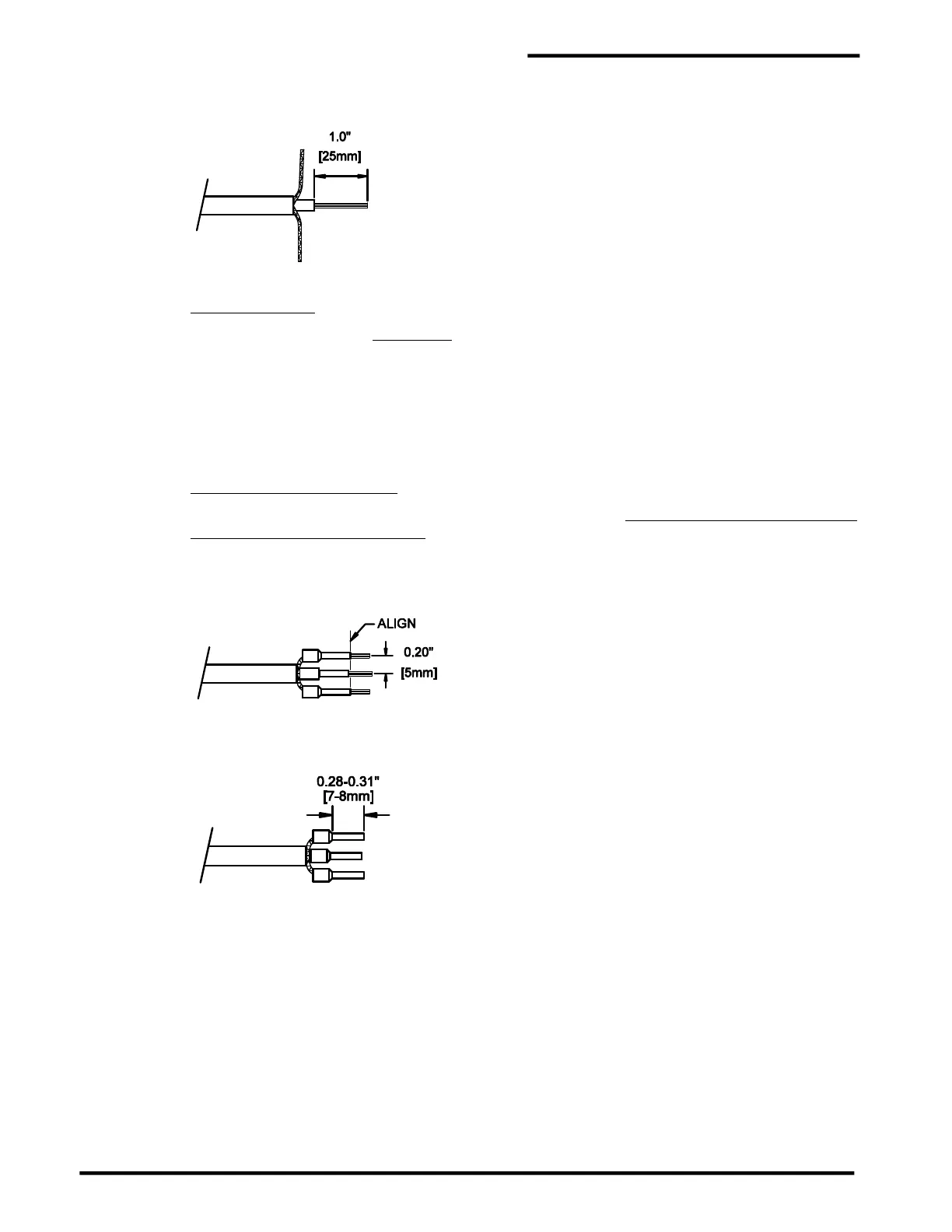
touching the sticky, water-blocking material. Twist each group into a small wire. Remove 1.0” [25
mm] of insulation from the center wire.
Step C JMP-U/-UD Cable
Slide a 14 AWG [2.5 mm²] uninsulated ferrule onto the center wire until it is tight against the center
insulation. Crimp the ferrule using a 2.5 mm² die. Then crimp it again with a 1.5 mm die. Slide a
16 AWG [1.5 mm²] insulated ferrule over each group of braid wire twisted strands. Spread the
ferrules apart to fit into the connector as shown. Align the ferrule ends as shown while minimizing
slack in the braid wire. Crimp the ferrules using a 1.0 mm crimp die.
JMP (from ZBA) or JPP Cable
Slide an 18 AWG (1.0mm²) insulated ferrule onto the center wire until the ferrule insulation is
completely over the wire insulation. Crimp the ferrule using a 0.50 mm crimp die. Slide an 18 AWG
(1.0mm²) insulated ferrule over each group of braid wire twisted strands. Spread the ferrules apart
to fit into the connector as shown. Align the ferrule ends as shown while minimizing slack in the
braid wire. Crimp the ferrules using a 0.50 mm crimp die.
Step D Trim excess wire from the end of the ferrules.
 Loading...
