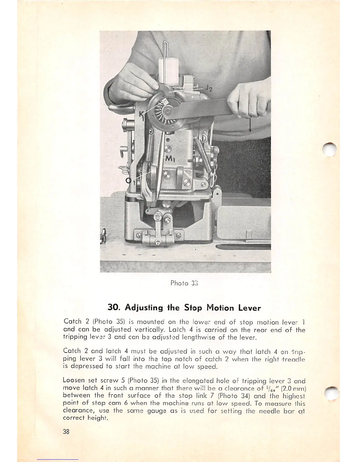
Photo
33
30.
Adjusting
fhe
Stop
Motion
Lever
Catch 2 (Photo
35)
is mounted on the lower end of stop motion lever 1
and con be
odjusted
vertically. Latch 4 is
carried
on the
rear
end
of
the
tripping lever 3 end can be
adjusted
lengthwise of the lever.
Catch 2 and latch 4 must be adjusted in such a way that latch 4 on trip
ping lever 3 will fall into the top notch of catch 2 when the right
treadle
is
depressed
to
start
the machine
at
low speed.
Loosen
set
screw 5 (Photo
35)
in the elongated hole of tripping lever 3 and
move latch 4 in such a manner that there will be a clearance of
^1^,"
(2.0
mm)
between the front surface of the stop link 7 (Photo
34)
and the highest
point of
stop
cam 6 when the machine runs
at
low
speed.
To
measure
this
clearance, use the same gauge as is used for setting the needle
bar
at
correct
height.
38