and
the
trimmer
snap
forword
toward
the
needle
thread.
Thereby
the
vertical
cam
N2 (Photo
24}
on the
movable
blade
of
the
needle
thread
trimmer
strikes
the
back
side
W
of
cam
guide
W, (Photo 23). As a
result,
the
trimmer
closes
and
the
thread
is
trapped
and
cut.
When re-storting the machine, the trimmer
bracket
Q is pulled
back
ond
pushed sufficiently
far
over
to the left by the
slanted
side
of
the .cam
guide W, so
that
the sprung lotch U will
again
be caught by
retainer
V.
Sprung latch U which yields
downwardly
should be held in position
about
Vj"
below
the
top
surface
of the
retainer
by
angle
X (Photo 23).
Retainer V must be
set
in such a
way
that
there will be a
clearance
of
.04"
between
sprung latch U
and
retainer
V when the trimmer is
retracted.
If
adjustment
is
required,
loosen
set
screw
Oi
and
move
the
retainer
V
as
may
be
required.
To avoid
damage
to the needle
thread
trimmer in
case
the knife cuts
too
early, guide screw Fj (Photo 24) of
bracket
Q is
provided
with a
taper
head
and
is
disposed
in such a
way
that
the slanted
edge
of the descending knife
bar
Mj will
force
the trimmer
bracket
Q bock so
as
to
keep
the knife from
striking
the
trimmer.
23.
The
Bobbin
Thread
Trimmer
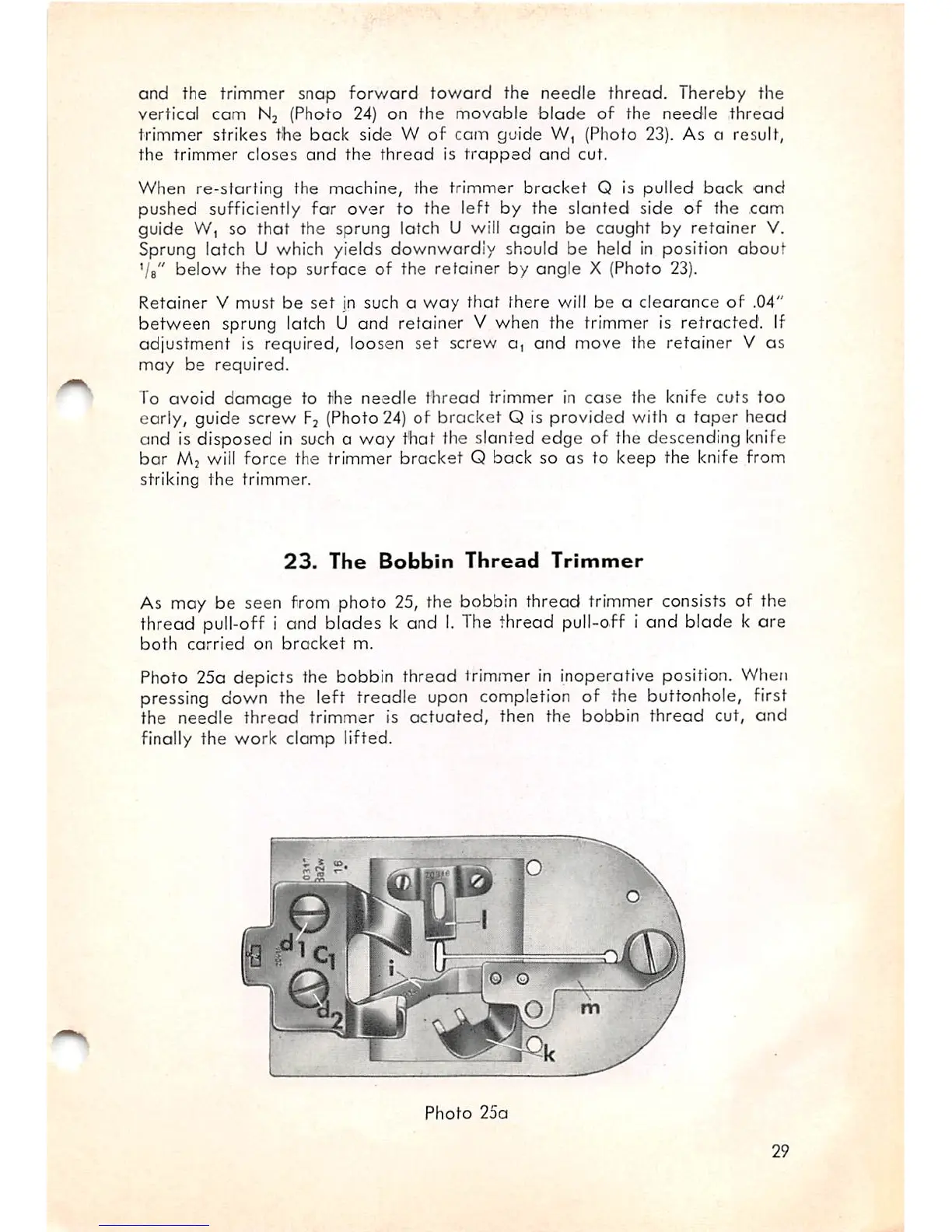
As may be seen from photo 25, the bobbin thread trimmer consists of the
thread pull-off i and blades k and
I.
The thread pull-off i and blade k ore
both
carried
on
bracket
m.
Photo 25a depicts the bobbin thread trimmer in inoperative position. When
pressing down the left treadle upon completion of the buttonhole, first
the
needle
thread
trimmer
is
actuated,
then
the
bobbin
thread
cut,
and
finally the work clamp lifted.
Photo
25a
29