When running the machine of low speed, latch 4 must enter the top notch
of catch 2;
at
high
speed,
it must fall into the lower notch.
To
adjust
the
distance
between
the tripping
dog
and
the tripping
segment,
switch
off
the
machine
and
turn
the
crank
until
the
feed
cam
is in
the
position
shown
in
photo
40.
33.
Adjusting
the
Hand
Stop
Lever
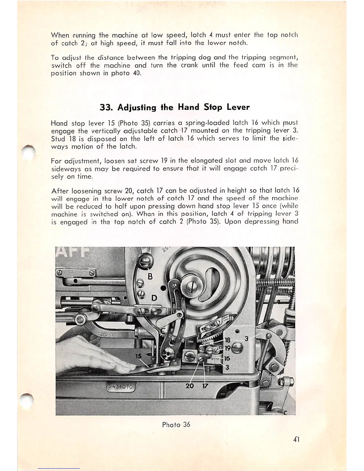
Hand stop lever 15 (Photo
35)
carries a spring-loaded latch 16 which
p>ust
engage the vertically adjustable catch 17 mounted on the tripping lever 3.
Stud 18 is
disposed
on the left of latch 16 which serves to limit the side
ways
motion
of
the
latch.
For adjustment, loosen
set
screw 19 In the
elongated
slot and move latch 16
sideways as may be required to ensure
that
it will engage catch 17 preci
sely
on
time.
After loosening screw 20, catch 17 can be adjusted in height so
that
latch 16
wilt engage in the lower notch of catch 17 and the speed of the machine
will be reduced to half upon pressing down hand stop lever 15 once (while
machine is switched on). When in this position, latch 4 of tripping lever 3
is engaged in the top notch of catch 2 (Photo
35).
Upon depressing hand
i
m
Photo
36
41